Journal of the Korean Wood Science and Technology
The Korean Society of Wood Science & Technology
Original Article

Bending Properties of Parallel Chord Truss with Steel-Web Members

Hyung Woo LEE1, Sang Sik JANG1,https://orcid.org/0000-0002-3124-7044
1Department of Biobased Materials, College of Agriculture & Life Science, Chungnam National University, Daejeon 34134, Korea
Corresponding author: Sang Sik JANG (e-mail: ssjang@cnu.ac.kr)

Copyright 2023 The Korean Society of Wood Science & Technology. This is an Open-Access article distributed under the terms of the Creative Commons Attribution Non-Commercial License (http://creativecommons.org/licenses/by-nc/4.0/) which permits unrestricted non-commercial use, distribution, and reproduction in any medium, provided the original work is properly cited.

Received: Nov 11, 2022; Revised: Dec 19, 2022; Accepted: Apr 09, 2023

Published Online: May 25, 2023

ABSTRACT

A truss is a structure in which the members are connected and arranged such that they are primarily subjected to axial loading. A truss has the advantage that it can be used for a longer span because the structure distributes the applied force to its members well, and the load is transmitted only in the axial direction of the members. Trusses manufactured using timber have more advantages than those made of other materials. In this study, the properties of parallel chord trusses composed of timber chord and steel-web members were evaluated. We constructed truss specimens with various lengths by using upper and lower chords of 2 × 4 inch spruce-pine-fir lumber and steel-web members manufactured by S and P companies. The specimens were tested in accordance with KS F 2150. The test results showed that the load at the deflection limit and the deflection limit itself increased from L/180 to L/360 regardless of the length of the specimens. For specimens of the same length, the load at the deflection limit increased as the height of the parallel timber chord truss specimens increased from 200 to 300 mm. Successive installations of the steel-web members (SST) showed almost 2 times the load at each deflection limit compared to that of SAT specimens (alternate installation of the steel-web members). When comparing the three load–deflection limits in terms of the manufacturer of the steel-web members, the load at each deflection limit for SST specimens was higher than that for PST specimens.

Keywords: truss structure; bending strength; parallel chord truss; steel-web member; deflection limit

1. INTRODUCTION

Many studies have been conducted on shear walls in timber construction (Jung et al., 2020; Lee and Jang, 2023). However, studies on roof and floor systems are not as numerous as those on shear walls. In timber construction, the deflection and creep of the floor and roof systems as well as the shear wall are important. For joists used in floor and roof systems, 2″ × 6″ or larger structural lumber should be used. When using structural lumber as a joist, there are restrictions on long spans. Owing to these problems, engineered wood such as glulam or CLT is mainly used and studied instead of structural lumber over long spans (Choi et al., 2020; Fujimoto et al., 2021; Yang et al., 2021). Galih et al. (2020) studied the mechanical properties of tropical hybrid cross-laminated timber using a bamboo-laminated board as the core layer. Park et al. (2020a) evaluated the bending creep properties of cross-laminated wood panels composed of tropical hardwoods and domestic temperate wood. Park et al. (2020b) tested the bending creep of glulam and bolted glulam under varying relative humidity. Choi et al. (2021) evaluated the flexural performance of ply lam CLT according to the plywood bonding method. Hwang et al. (2022) monitored the moisture and dimensional behavior of a nail-laminated timber concrete slab exposed to an outdoor environment. In addition to glulam and CLT, truss is a bending member that can be used for long spans. A truss is a structure in which the members are connected and arranged such that they are primarily subjected to axial loading. A truss has the advantage that it can be used for a longer span because the structure distributes the applied force to its members well, and the load is transmitted only in their axial direction. Trusses manufactured using timber have more advantages than those made of other materials. The advantages of timber trusses include the following: 1) Timber trusses are usually more cost-effective than metal trusses; 2) Wood trusses offer excellent thermal properties, particularly compared to steel; 3) Timber trusses are more flexible and versatile than those manufactured using other materials. Owing to these advantages, numerous studies on trusses have been conducted worldwide. Šilih et al. (2005) designed plane timber trusses by considering joint flexibility. Komatsu et al. (2018) experimentally and numerically analyzed the nonlinear behavior of wooden parallel chord trusses composed of self-tapping screws. However, only a few studies have been conducted on timber trusses in South Korea. Cha (1992) studied metal and plywood gusset plate connections for light-frame wood truss tension joints. Kim et al. (2014) studied the strength and application of OSB gusset trusses in field assemblies.

A truss in which the chord is made of timber and web members are made of steel is easier to manufacture than a truss in which both the chord and web members consist of timber. Moreover, it has the advantages of being cheaper, lighter to lift, and faster to install. Trusses consisting of timber chords and steel-web members have also been developed in other countries. Isopescu and Gavriloaia (2015) determined the model damping ratio of a hybrid floor system composed of timber chord and metal web members. Lennon et al. (2010) conducted a natural fire test on three engineered timber floor systems, including a timber truss incorporating upper and lower solid-timber chord members, and a pressed steel-web member.

In this study, a parallel chord truss was manufactured using steel-web members of a domestic company, S Co., and foreign company, P Co., for roof and floor systems. The bending properties of the two parallel-chord trusses were evaluated and compared.

2. MATERIALS and METHODS

2.1. Materials
2.1.1. Timber chord members

In this study, to manufacture truss specimens, northern SPF No. 2 2 × 4 inch lumbers were used for the upper and lower chords. For all truss specimens, the upper and lower chord members were made of one piece of lumber without a lengthwise connection.

2.1.2. Steel-web members

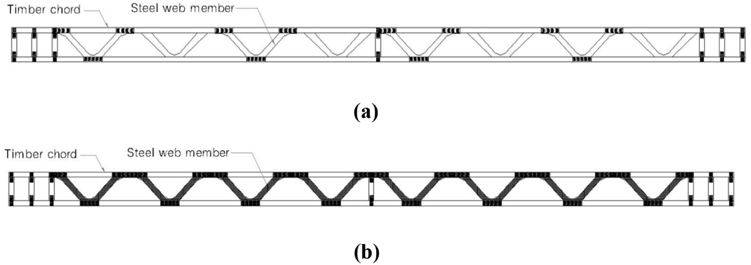
Concerning the steel-web members, two different types of steel-web materials, produced domestically and abroad, were used to compare their performance. The shapes and dimensions of the steel-web members used in this study are shown in Fig. 1 and listed in Table 1. Fig. 1(a) depicts a steel-web member manufactured by S Co., a domestic company. Fig. 1(b) shows the steel- web manufactured by P Co., a foreign company.

wood-51-3-197-g1
Fig. 1. Steel-web members. (a) Shape of the steel-web member manufactured by S Co., a domestic company, (b) shape of the steel-web member manufactured by P Co., a foreign company.
Download Original Figure
Table 1. Specification of the steel-web members
Steel web-member Material a (mm) b (mm) L (mm) h (mm) d (mm)
S Co. Z275M280 100 135 600 200
250
300
7.34
P Co. Z275M220 70 160 610 250
300
13
Download Excel Table
2.1.3. Truss specimen

The parallel timber chord truss with steel-web (PCTSW) specimens used in this study were composed of timber chords and steel-web members, as depicted in Fig. 2, and are constructed as shown in Table 2. Note from this figure that the SAT specimen was manufactured by alternate installation of the steel-web members on both sides using those produced by the S company; SST and PST specimens were manufactured by continuous installation of the steel-web members on both sides using those produced by the S and P companies, respectively.
wood-51-3-197-g2
Fig. 2. PCTSW specimen. (a) SAT specimen, (b) SST and PST specimen. PCTSW: parallel timber chord truss with steel-web, SAT: S company’s steel web.-Alternate installation-truss, SST: S company’s steel web.-Successive installation-truss, PST: P company’s steel web.-Successive installation-truss.
Download Original Figure
Table 2. Specification of the PCTSW specimens
Symbol Web members Height (mm) Length (m)
Type Installation method
SAT200-3.6 S. Co Alternate 200 3.6
SAT200-4.2 200 4.2
SAT200-4.8 200 4.8
SAT250-4.2 250 4.2
SAT250-4.8 250 4.8
SAT250-5.4 250 5.4
SAT300-4.8 300 4.8
SAT300-5.4 300 5.4
SAT300-6.0 300 6.0
SST200-4.8 S. Co Succession 200 4.8
SST250-5.4 250 5.4
SST300-6.0 300 6.0
PST250-5.4 P. Co Succession 250 5.4
PST300-6.0 300 6.0

PCTSW: parallel timber chord truss with steel-web, SAT: S company’s steel web.-Alternate installation-truss, SST: S company’s steel web.-Successive installation-truss, PST: P company’s steel web.-Successive installation-truss.

Download Excel Table

As listed in Table 2, the SAT specimens were manufactured using domestic S Co.; these specimens featured five different lengths and three different heights. The SST specimens were manufactured using domestic S Co.; they presented three different heights and lengths. The PST specimens were manufactured using imported P Co. and had two different heights and lengths.

2.2. Test method

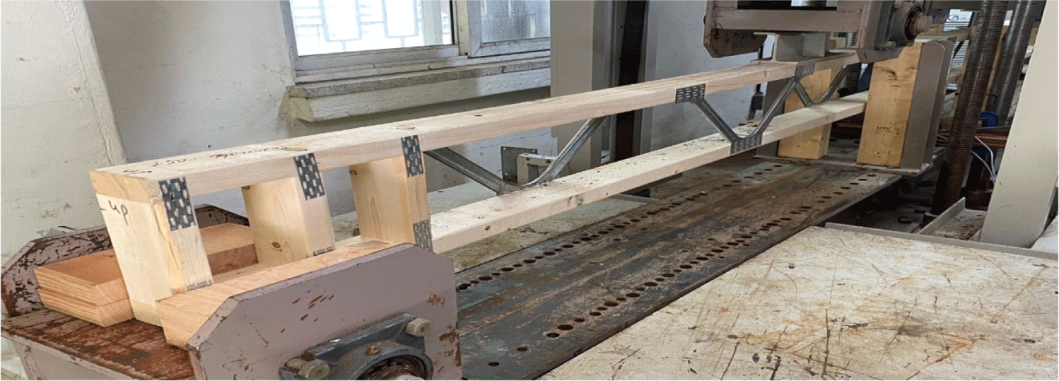
The bending tests were performed in accordance with KS F 2150 to evaluate the bending properties of the truss specimens, as shown in Fig. 3 (Korea Standard Association, 2020). Note that the loading points were adjusted such that the load acted through the joints located at approximately 1/3 of the span. During the test, the deflection was measured using two linear variable differential transformers (LVDTs) attached to both sides at the middle of the specimen, and the average of two LVDTs measurements was recorded to determine the deflection of the specimen.
wood-51-3-197-g3
Fig. 3. Testing method to determine the bending properties of a PCTSW specimen in accordance with KS F 2150. PCTSW: parallel timber chord truss with steel-web.
Download Original Figure
2.3. Calculations

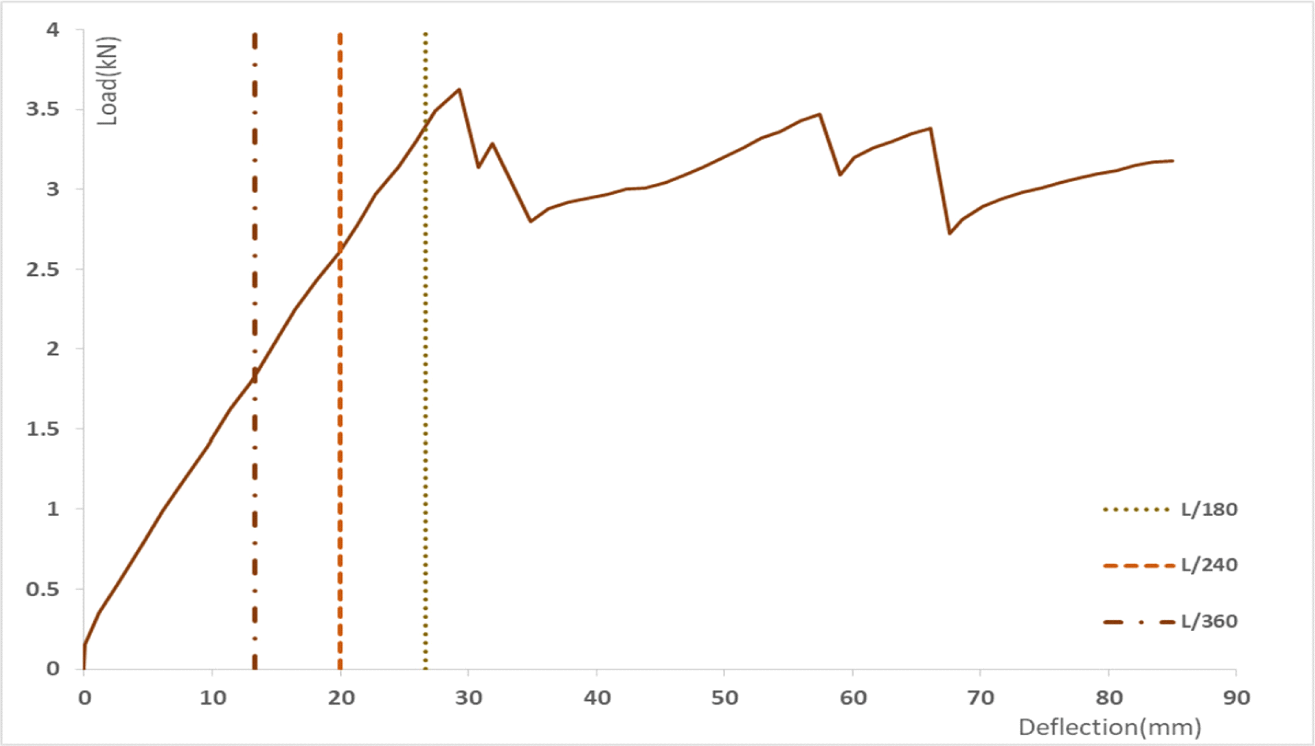
Load–deflection diagrams similar to the graph shown in Fig. 4 were obtained from the bending tests of the PCTSW specimens.
wood-51-3-197-g4
Fig. 4. Load-deformation diagram obtained from the bending test for SST200-4.8. SST: S company’s steel web.-Successive installation-truss.
Download Original Figure

In Fig. 4, the dotted lines indicate the deflection limits of 1/360, 1/240, and 1/180 of the span, which can be applied to the design according to the loading conditions. The deflection limits obtained from KDS 41 50 20 (Ministry of Land, Infrastructure and Transport, 2022a) and KDS 41 50 70 (Ministry of Land, Infrastructure and Transport, 2022b), which depend on the deflection limit under loading conditions, are listed in Table 3.

Table 3. Deflection limits according to the loading conditions
Building code Use classification Live load Total load (Live load + dead load)
KDS 41 50 70 Roof beam L/240 L/180
Floor beam L/360 L/240
KDS 41 50 20 Roof and floor beam L/360 L/240
Download Excel Table

3. RESULTS and DISCUSSION

3.1. Loads at deflection limits

From the results of the bending tests for the PCTSW in this study, the loads at three deflection limits were obtained for each PCTSW specimen, as listed in Table 4.

Table 4. Results of the bending test for each PCTSW
Specimen Load at deflection limit (kN)
L/180 L/240 L/360
SAT200-3.6 1.41 1.16 0.83
SAT200-4.2 1.88 1.70 1.27
SAT200-4.8 1.50 1.32 0.99
SAT250-4.2 2.64 2.37 1.75
SAT250-4.8 1.90 1.61 1.21
SAT250-5.4 1.57 1.51 1.09
SAT300-4.8 1.46* 1.60 1.29
SAT300-5.4 1.62 1.50 1.15
SAT300-6.0 1.49* 1.81 1.09
SST200-4.8 3.25 2.57 1.80
SST250-5.4 3.35 2.68 1.93
SST300-6.0 2.91* 3.53 2.56
PST250-5.4 2.91 2.28 1.59
PST300-6.0 4.01 3.24 2.35

The maximum load was reached before the deflection limit.

PCTSW: parallel timber chord truss with steel-web, SAT: S company’s steel web.-Alternate installation-truss, SST: S company’s steel web.-Successive installation-truss, PST: P company’s steel web.-Successive installation-truss.

Download Excel Table
3.2. Failure mode

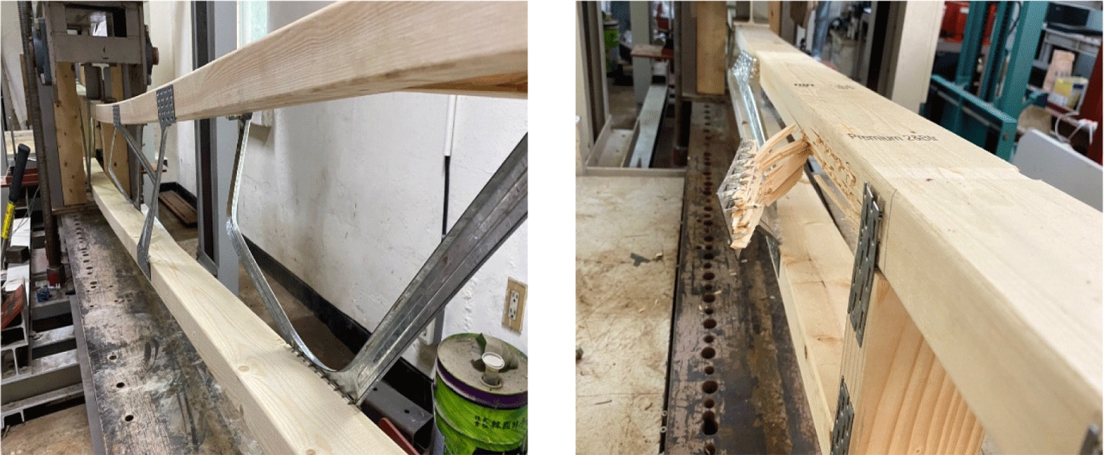
Fig. 5 shows the failure modes in the bending tests of the PCTSW specimens. In all the test specimens, failure occurred because of the shear force rather than the bending moment. The steel-web member was bent by the shear force. Subsequently, the joint between the steel-web member and upper chord failed.
wood-51-3-197-g5
Fig. 5. Failure mode in bending test for PCTSW specimens. PCTSW: parallel timber chord truss with steel-web.
Download Original Figure
3.3. Effect of the length and height of specimen

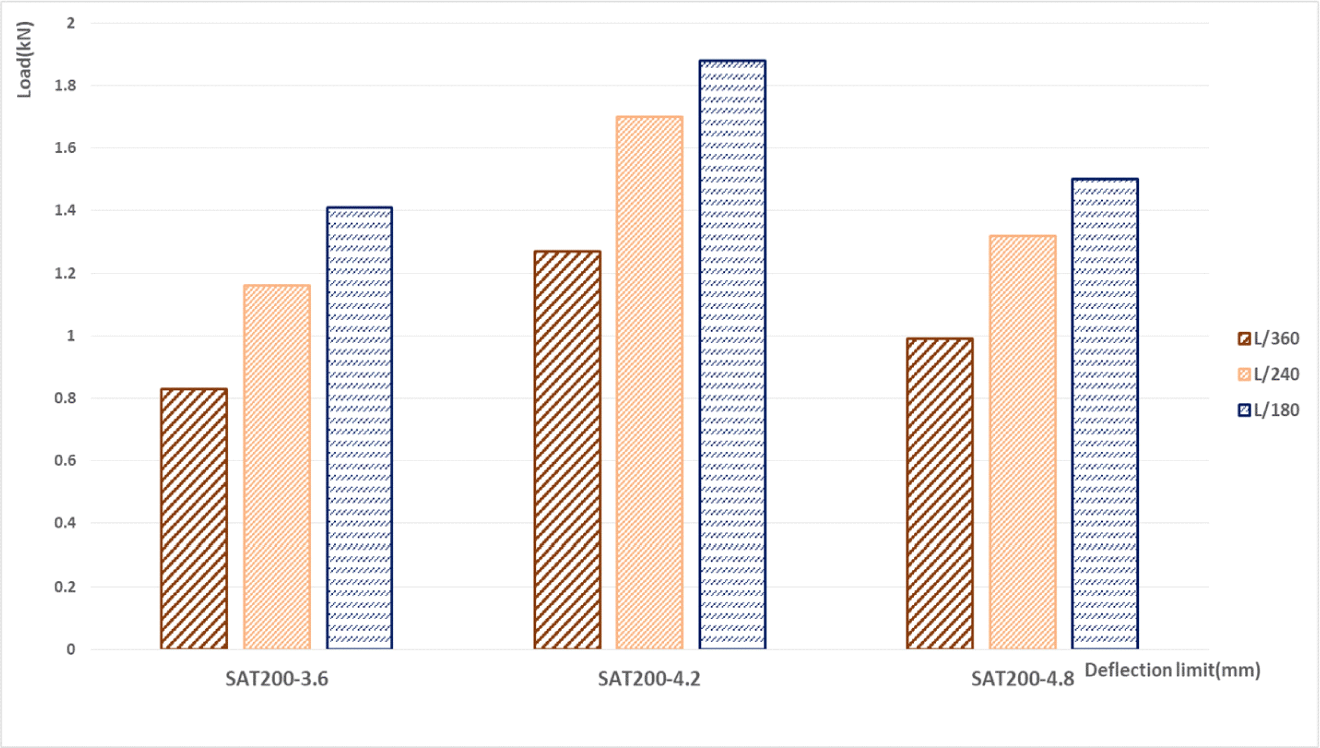
Fig. 6 depicts the change in load at three deflection limits for the SST 200 specimen featuring the same height but different lengths. This shows the effect of the length of PCTSW specimens. According to Fig. 6, the load at the deflection limit and the deflection limit itself increased from L/360 to L/180 regardless of the lengths of the specimen. Some trends were observed for all the specimens, as shown in Table 4.
wood-51-3-197-g6
Fig. 6. Comparison of the loads at three deflection limits for SAT200 specimens. SAT: S company’s steel web.-Alternate installation-truss.
Download Original Figure

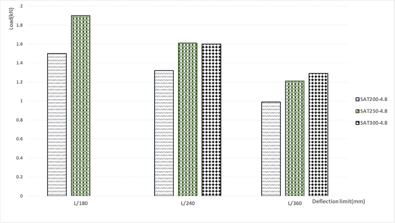
Fig. 7 shows the change in load at three deflection limits for SAT specimens. Load at the deflection limit increased as the height of PCTSW specimens increased from 200 to 300 mm.
wood-51-3-197-g7
Fig. 7. Comparison of the loads at three deflection limits for SAT specimens of the same length. SAT: S company’s steel web.-Alternate installation-truss.
Download Original Figure
3.4. Effect of the installation method of steel-web members

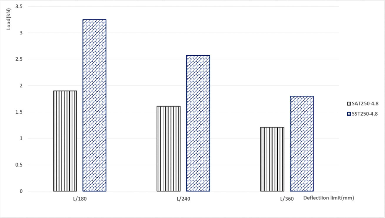
Fig. 8 shows the change in load at three deflection limits for SAT and SST specimens with the same height and length. For successive installation of the steel-web members (SST), approximately 1.4–1.7 times higher load was measured at each deflection limit than that of SAT specimens (alternate installation of the steel-web members).
wood-51-3-197-g8
Fig. 8. Comparison of the loads at three deflection limits for SAT and SST specimens. SAT: S company’s steel web.-Alternate installation-truss, SST: S company’s steel web.-Successive installation-truss.
Download Original Figure
3.5. Effect of the type of steel-web member

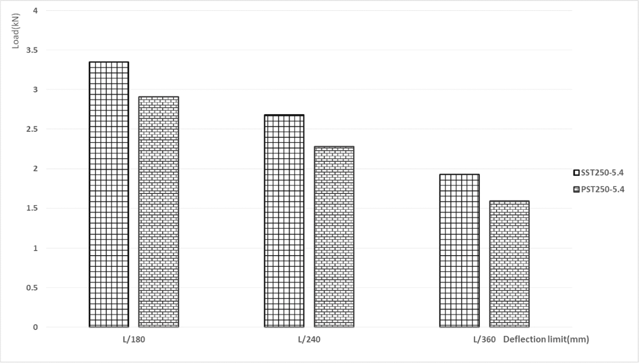
The changes in load at three deflection limits for different steel-web members is shown in Fig. 9. The load at each deflection limit for SST specimens (using steel-web members manufactured by S Co.). were higher than those of PST specimens (using steel-web members manufactured by P Co.). As described in Section 3.2., in all the test specimens, the steel-web members were bent by the shear force. Thus, this difference, which depends on the manufacturer of the steel-web member, is attributed to the material.
wood-51-3-197-g9
Fig. 9. Comparison of the load at deflection limits for different types of steel-web members.
Download Original Figure

4. CONCLUSIONS

In this study, PCTSW specimens were constructed using timber chords and steel-web members. The bending strength of various types of PCTSW specimens according to their length and height, installation method of steel-web members, and type of steel-web member were tested according to KS F 2150. From the analysis of the test results, the following conclusions were drawn:

  1. The load at deflection limits and the deflection limits themselves increased from L/180 to L/360 regardless of the lengths of specimens.

  2. The load at deflection limits increased as the height of PCTSW specimens increased from 200 to 300 mm.

  3. The successively installed steel-web members (SST) showed almost 2 times higher load at each deflection limit compared with that of SAT specimens (alternate installation of the steel-web members).

  4. The load at each deflection limit for SST specimens (using steel-web members manufactured by S Co.) was higher than that of PST specimens (using steel-web members manufactured by P Co.).

CONFLICT of INTEREST

No potential conflict of interest relevant to this article was reported.

ACKNOWLEDGMENT

Not applicable.

REFERENCES

1.

Afolayan, J.O. 1998. Economic efficiency of glued joints in timber truss systems. Building and Environment 34(2): 101-107.

2.

Cha, J.K. 1992. Study on metal plate connections and plywood gusset plate connections for light-frame wood truss tension joint. Journal of the Korean Wood Science and Technology 20(1): 46-50.

3.

Choi, G.W., Yang, S.M., Lee, H.J., Kim, J.H., Choi, K.H., Kang, S.G. 2020. A study on the block shear strength according to the layer composition of and adhesive type of ply-lam CLT. Journal of the Korean Wood Science and Technology 48(6): 791-806.

4.

Choi, G.W., Yang, S.M., Lee, H.J., Kim, J.H., Choi, K.H., Kang, S.G. 2021. Evaluation of flexural performance according to the plywood bonding method of ply-lam CLT. Journal of the Korean Wood Science and Technology 49(2): 107-121.

5.

Fujimoto, Y., Tanaka, H., Morita, H., Kang, S.G. 2021. Development of ply-lam composed of Japanese cypress laminate and Korean larch plywood. Journal of the Korean Wood Science and Technology 49(1): 57-66.

6.

Galih, N.M., Yang, S.M., Yu, S.M., Kang, S.G. 2020. Study on the mechanical properties of tropical hybrid cross laminated timber using bamboo laminated board as core layer. Journal of the Korean Wood Science and Technology 48(2): 245-252.

7.

Hwang, S.W., Chung, H., Lee, T., Ahn, K.S., Pang, S.J., Bang, J., Kwak, H.W., Oh, J.K., Yeo, H. 2022. Monitoring of moisture and dimensional behaviors of nail-laminated timber (NLT)-concrete slab exposed to outdoor air. Journal of the Korean Wood Science and Technology 50(5): 301-314.

8.

Isopescu, D., Gavriloaia, C. 2015. Determination of modal damping ratio for a hybrid floor system. Journal of Vibroengineering 17(4): 1961-1970.

9.

Jung, H., Song, Y., Hong, S. 2020. Effect of glass fiber-reinforced connection on the horizontal shear strength of CLT walls. Journal of the Korean Wood Science and Technology 48(5): 685-695.

10.

Kim, T.W., Ha, B., Jang, S.S. 2014. The strength and applications of OSB gusset trusses for field assembly. Journal of the Korean Wood Science and Technology 42(6): 708-713.

11.

Komatsu, K., Teng, Q., Li, Z., Zhang, X., Cai, W., Que, Z. 2018. Experimental and numerical analyses on nonlinear behaviour of wooden parallel chord trusses composed of self-tapping screws. Journal of Wood Science 64(6): 776-793.

12.

Korea Standard Association. 2020. Method of Static Bending Test for Full Sized Structural Lumber. KS F 2150. Korea Standard Association, Seoul, Korea.

13.

Lee, H.W., Jang, S.S. 2023. Lateral resistance of reinforced light-frame wood shear walls. Journal of the Korean Wood Science and Technology 51(1): 58-66.

14.

Lennon, T., Hopkin, D., EI-Rimawi, J., Silberschmidt, V. 2010. Large scale natural fire tests on protected engineered timber floor systems. Fire Safety Journal 45(3): 168-182.

15.

Ministry of Land, Infrastructure and Transport. 2022a. Standard Wood Structure for Member Design. KDS 41 50 20. Ministry of Land, Infrastructure and Transport, Sejong, Korea.

16.

Ministry of Land, Infrastructure and Transport. 2022b. Standard Wood Structure for Light Frame Timber Structure. KDS 41 50 70. Ministry of Land, Infrastructure and Transport, Sejong, Korea.

17.

Park, H.M., Gong, D.M., Shin, M.G., Byeon, H.S. 2020a. Bending creep properties of cross-laminated wood panels made with tropical hardwood and domestic temperate wood. Journal of the Korean Wood Science and Technology 48(5): 608-617.

18.

Park, J., Song, Y., Hong, S. 2020b. Bending creep of glulam and bolted glulam under changing relative humidity. Journal of the Korean Wood Science and Technology 48(5): 676-684.

19.

Šilih, S., Premrov, M., Kravanja, S. 2005. Optimum design of plane timber trusses considering joint flexibility. Engineering Structures 27(1): 145-154.

20.

Yang, S.M., Lee. H.H., Kang. S.G. 2021. Research trends in hybrid cross-laminated timber (CLT) to enhance the rolling shear strength of CLT. Journal of the Korean Wood Science and Technology 49(4): 336-359.