1. INTRODUCTION
Thinned small larch logs having small diameter do not have specific value-added final use except wood chip, pallet or fuel wood which are products having very low economic value. Even though larch small logs do not have any value-added final usage at present time, their mechanical properties are strong enough to be used for structural purposes (Jang, 2012; Jang, 2015). In the previous researches (Jang, 2012; Jang, 2015), sawn timbers produced from small larch logs were proved to be strong enough as laminations for structural glulam. In those researches, small larch logs were sawn to square timbers containing pith at centre, which were used as inner-laminations for structural glulam for bending and any laminations for structural glulam for compression. Moreover, in both cases, they showed sufficient structural performance under bending and compressive loads and were proved to have enough stiffness and strength to be used as structural members.
The idea of manufacturing CLT was started to consume more wood and to develop stronger wooden members for high-rise buildings (Blass, 2004). Dujic, et al. (2006) tested CLT wall panels under actual boundary conditions and Mestek, et al. (2008) proposed the design method of CLT panels. In recent days, many researchers have concern on CLT and performed a lot of researches, and the results of their efforts was summarized as CLT Handbook for Canada (Gagnon and Pirvu, 2011) and for the U.S. (Karacabeyli and Douglas, 2013).
CLT construction has become a new trend in the world, and more and more people in Korea also have interest in CLT construction. In Korea, Song and Hong (2016) evaluated the bonding properties of CLT manufactured by larch lumber, Pang, et al. (2017) evaluated bending properties with nailed CLT members loaded perpendicular to plane, and Oh, et al. (2017) tested about the adequate end distance for single-shear screw connection in CLT. However, good quality timbers produced in Korea are so expensive that CLT manufactured by using those has economically no competitive power with other construction materials. The method of importing timbers for CLT manufacturing is not a good idea because it is still expensive compared with the imported CLT manufactured in other countries. It is also not a good idea in terms of environmental consideration because importing timber or CLT from other countries include consuming oils for transportation and producing additional CO2.
Therefore, the idea of manufacturing CLT with small square timbers and plywood, which are both relatively low price in Korea, was developed to manufacture CLT that is economically competitive with other materials. Small square timbers were already proved to have enough stiffness and strength as a structural material. Therefore, CLT panels manufactured by using small square timbers were also expected to have enough strength to be used as vertical and horizontal diaphragms. In this study, straight small larch logs were selected, sawed, dried and finished to produce square timbers with 90 mm × 90 mm cross section, which were glued laterally to form core panels used to manufacture CLT wall panels. In addition, 12 mm thick structural plywood panels were used as cross bands to manufacture three-ply CLT wall panels by covering the surface and the back of larch square timber core panel.
2. MATERIALS and METHODS
In this study, larch logs having age less than 18 years, diameter between 120 mm~150 mm, and straight shape were selected among the thinned small logs. They were sawed to 105 mm × 105 mm square timbers by the method as shown in Fig. 1.
Sawn timbers were dried to the target moisture content of 15% by applying the following drying schedule to minimize drying defects developed during the drying process:
Moisturizing for 12 hours at 96°C
High temperature drying for 36 hours at dry bulb temperature of 120°C and wet bulb temperature of 90°C
Medium temperature drying for 24 hours at dry bulb temperature of 100°C and wet bulb temperature of 70°C
Low temperature drying for 24 hours at dry bulb temperature of 80°C and wet bulb temperature of 60°C
Conditioning for 3 days at room temperature
The dried timbers were finished to produce small square timbers having cross section of 90 mm × 90 mm. These small square timbers were visually graded in accordance with the quality standard for lamination given in KS F 3021. Results of visual grading for small square timbers are No. 1(18.8%), No. 2(37.7%), No. 3(37.0%) and No. 4(6.5%), among which all the small square timbers except No. 4 were used to produce core panels for CLT. Small square timbers were glued together laterally to form 1,220 mm × 2,440 mm panels, which were used as cores for CLT wall panels.
No. 1 grade of structural plywood conforming to KS F 3113 having size of 1,220 mm × 2,440 mm, produced in Korea, were used as cross band covering the surfaces and the backs of small square timber cores to manufacture 3 ply CLT wall panels. The thickness of plywood used to manufacture CLT was 12 mm, and their bending strength and stiffness were 25.5 MPa and 5.5 GPa parallel to strong axis, and 19.5 MPa and 3.5 GPa parallel to weak axis.
The adhesive of brand name Okong (acetylated vinyl based glue) was used to make bonding between core and cross band. When making adhesion between core and cross band, the glue spreading rate was 150 g/m2. The pressure required to make a strong bonding was applied by two method. The first method was application of 1 MPa of pressure for 2 hours, which produced the specimen named CGCLT. The second method was nailing of 8d nails with 150 mm spacing along the edge and 300 mm spacing in the field, which produced the specimen named NGCLT. In NGCLT specimen, the spacing between rows of nails was 400mm and nails applied pressure to plywood face and small square timber core. The advantage of nailing was that it is not required to keep the pressure for two hours until the bond cures completely. Therefore, CLT products can be released right after nailing and can save time for production of CLT. CLT wall panel specimens were manufactured with one long edge of tongue and the other long edge of groove as shown in Fig. 2 so that T&G parallel joints are possible between CLT wall panels.
Nailing patterns applied to manufacture NGCLT specimen is shown in Fig. 3, in which patterns (a) and (b) were applied to the surface plywood and the back plywood, respectively.
The CLT wall panels with T&G edge manufactured at factory can be moved to construction site and the adjacent CLT panels can be joined together to form parallel T&G joint as shown in Fig. 4 to make vertical diaphragm.
Before making T&G joints between two CLT wall panels, adhesives were spread thoroughly on groove part, and tongue part was pressed into the groove. To make a secure T&G joint between CLT panels, 8d nails were used with 100mm spacing along the edge on both sides.
To compare the lateral resistance of CLT wall panels with three other types of well-known vertical diaphragms, specimens of conventional light-frame timber shear walls (S150 (common conventional type) and S100 (reinforced conventional type) specimens) and mid-ply shear wall system(MP specimen) were constructed. S150 specimen was constructed with 38 mm × 89 mm dimension lumber framing with 406 mm spacing, 11.1 mm thick OSB as sheathing, and nailing of 8d nails with 150 mm edge nail spacing and 300 mm field nail spacing. 16d nails were used for joints between framing members. S100 specimen has the same composition as S150 specimen except that nail spacing was reduced to 100 mm along the edge and 200 mm in field. MP (Mid-ply) shear wall system developed in Canada was also selected to compare their lateral resistance with CLT wall panels. MP specimen was constructed by applying the standard manufacturing method for single MP shear wall system as shown in Fig. 5.
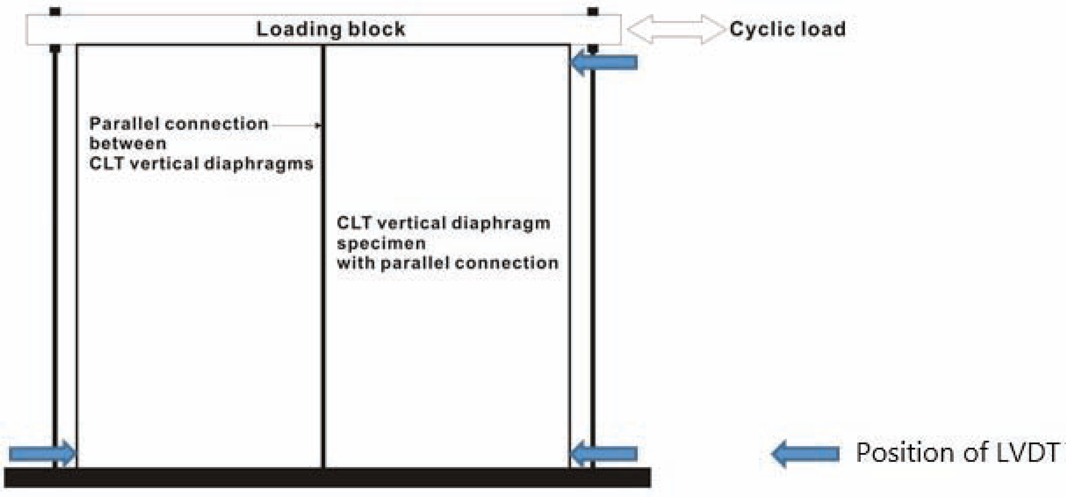
The lateral-load resistance tests were performed in accordance with KS F 2154. To investigate the lateral resistance of CLT wall panels under horizontal loads, the testing method given in KS F 2154 was applied as shown in Fig. 5. During the tests, displacement was measured at three point including bottom at both ends and top right-hand side. To compare the lateral-load resistance of CLT wall panel with other types of shear walls including the conventional light framing and mid-ply shear wall, lateral load resistance tests as shown in Fig. 6 were performed with S150, S100, MP, CGCLT and NGCLT specimens. No. of replication was 3 for each specimen type. In Fig. 6, the width and height of specimen were 2,440 mm × 2,440 mm and 90 mm × 90 mm sill plates were installed by using anchor bolts of 15 mm diameter with 300mm spacing. For S150 and S100 specimen, the bottom plate was fixed to the sill plate by nailing two 16d nails with 406 mm spacing and hold down connector was installed at both ends of the specimen. For MP and CLT specimens, 200 mm × 200 mm steel plates of 6mm thickness were used to connect between the specimen and the sill plate with 610 mm spacing at each surface. At both ends of MP and CLT specimens, two 900mm long steel straps were installed at each end instead of hold down. For steel plate connections, 10 screws of 38mm length were installed at sill plate and specimen, respectively. For steel strap connections at both ends, two steels straps were inserted into the bottom of the sill plate at each end and they were bent to upright position, and 10 screws of 38 mm length were installed at one end of a steep strap, respectively.
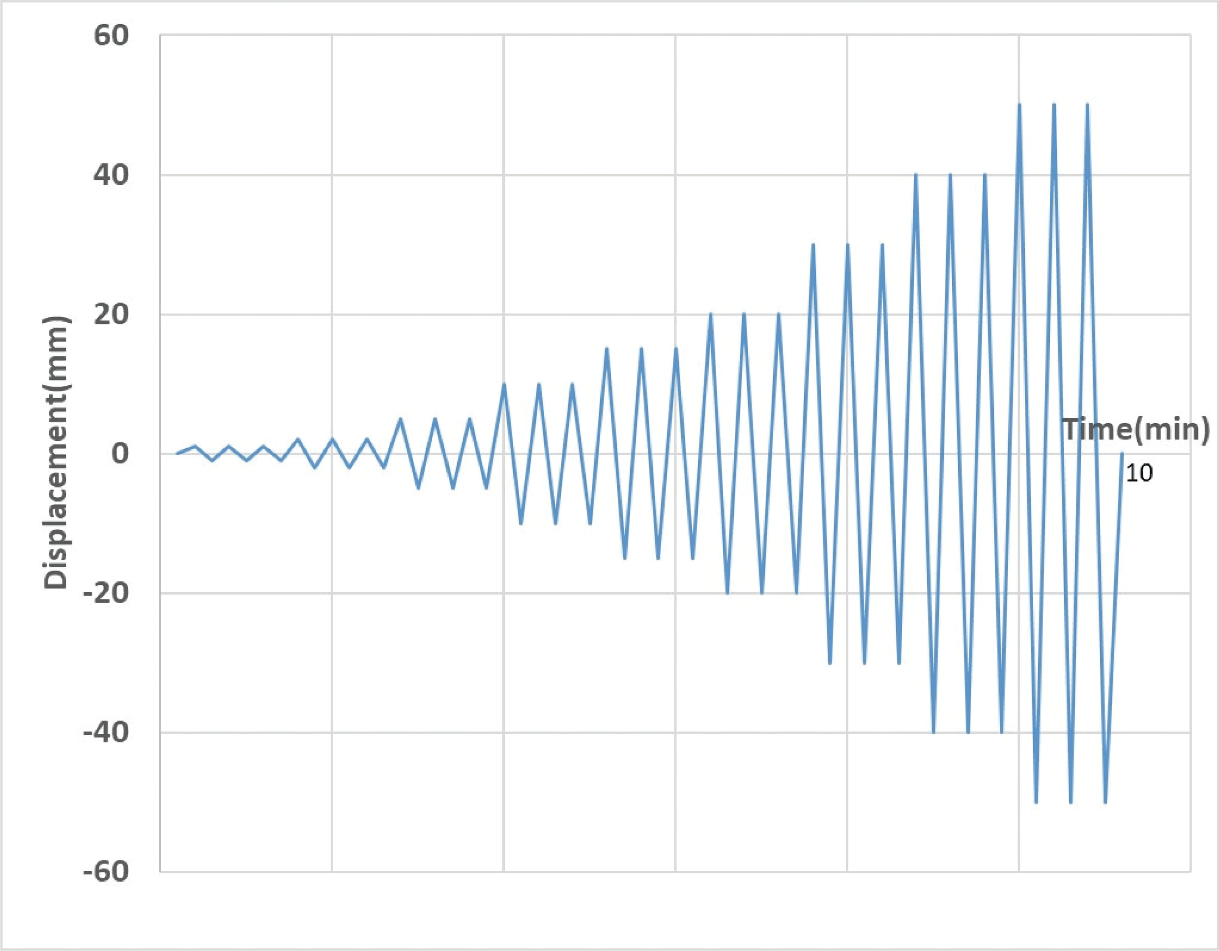
The lateral load applied to the specimen in Fig. 6 was quasi-static cyclic load having load function as shown in Fig. 7. The load function in Fig. 7 was composed of 9 steps including 1 mm, 2 mm, 5 mm, 10 mm, 15 mm, 20 mm, 30 mm, 40 mm and 50 mm displacement and each loading step was composed of three replications.
The ultimate shear strength and the apparent shear stiffness were calculated from the test results by using equations (1) and (2).
in which, Su: Ultimate shear strength (N/m)
Pu: Maximum load or the load at 50mm displacement (N)
b: Width of the specimen (m)
in which, G: Apparent shear stiffness (N/mm)
P: The load equal to 1/3 of the maximum load (N)
a: Height of specimen (mm)
b: Width of the specimen (mm)
d: Total displacement (mm)
3. RESULTS and DISCUSSION
The load-displacement diagrams obtained from the lateral-load resistance tests are given in Fig. 8 for S150 specimen, Fig. 9 for S100 specimen, Fig. 10 for MP specimen, Fig. 11 for CGCLT specimen and Fig. 12 for NGCLT specimen.
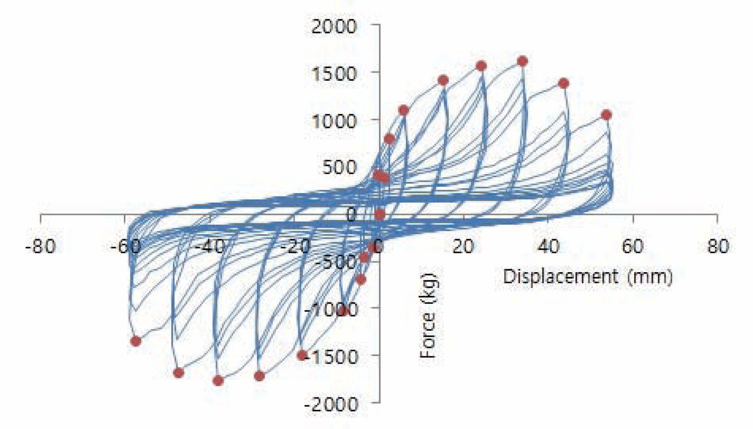
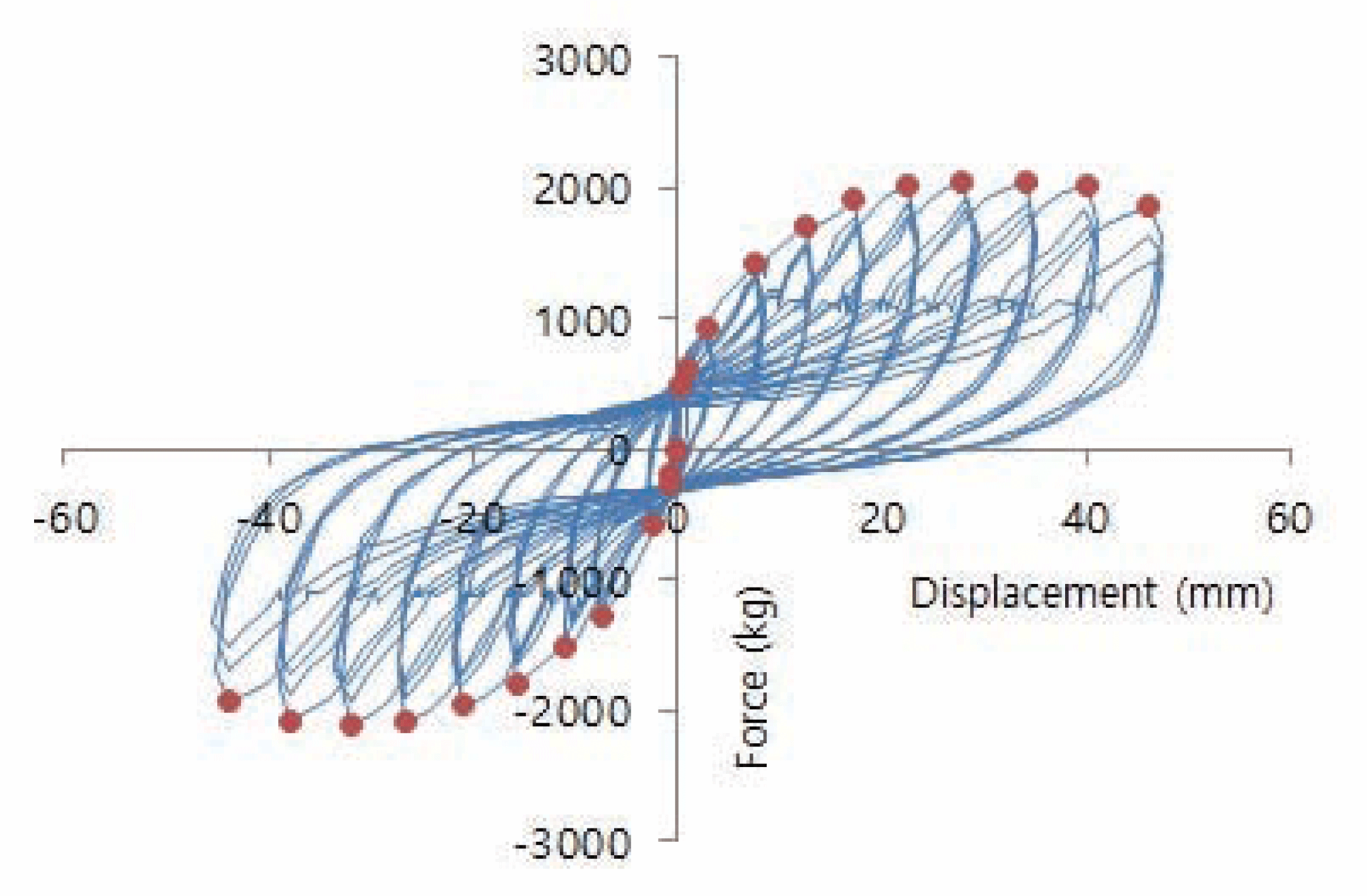
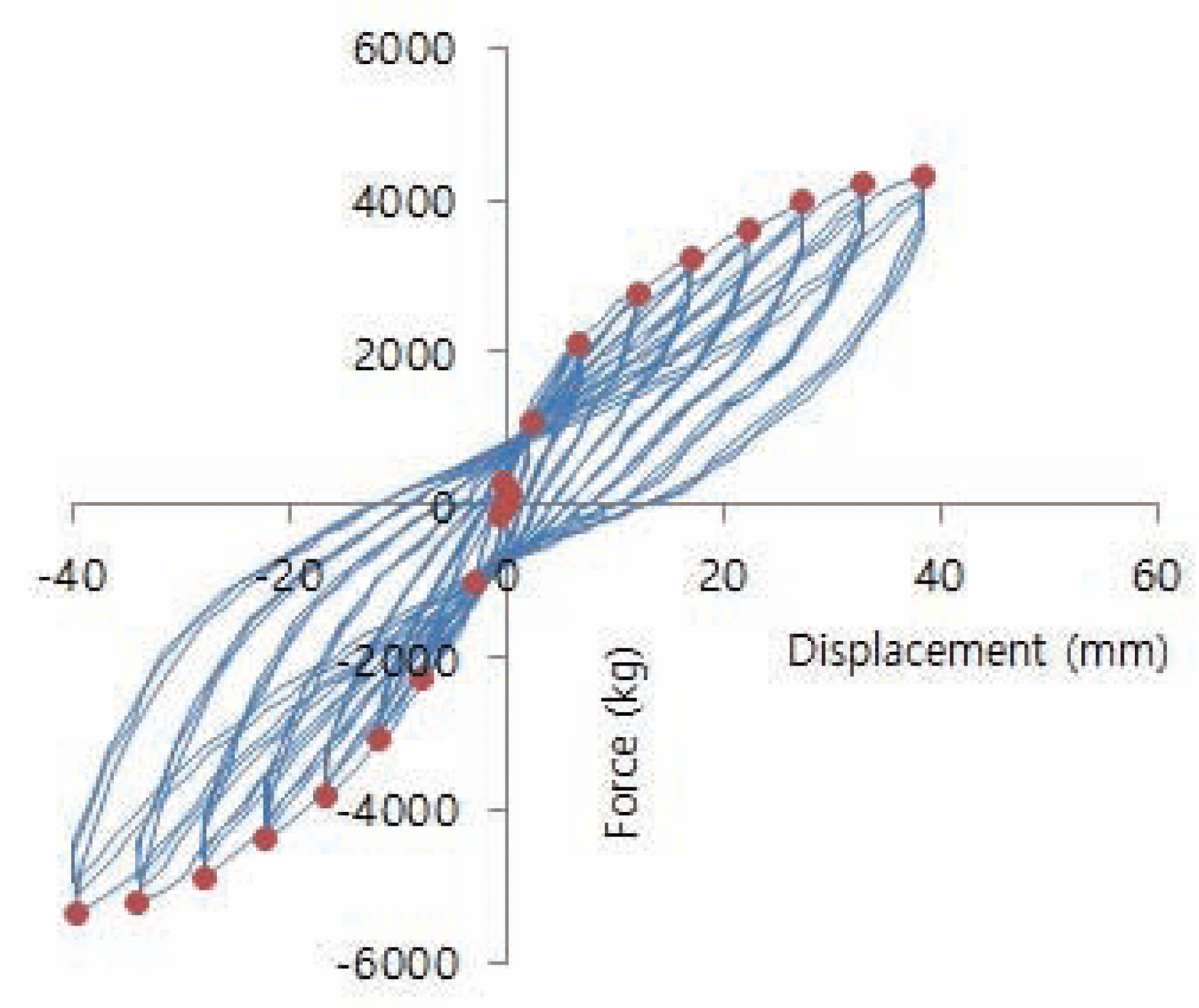
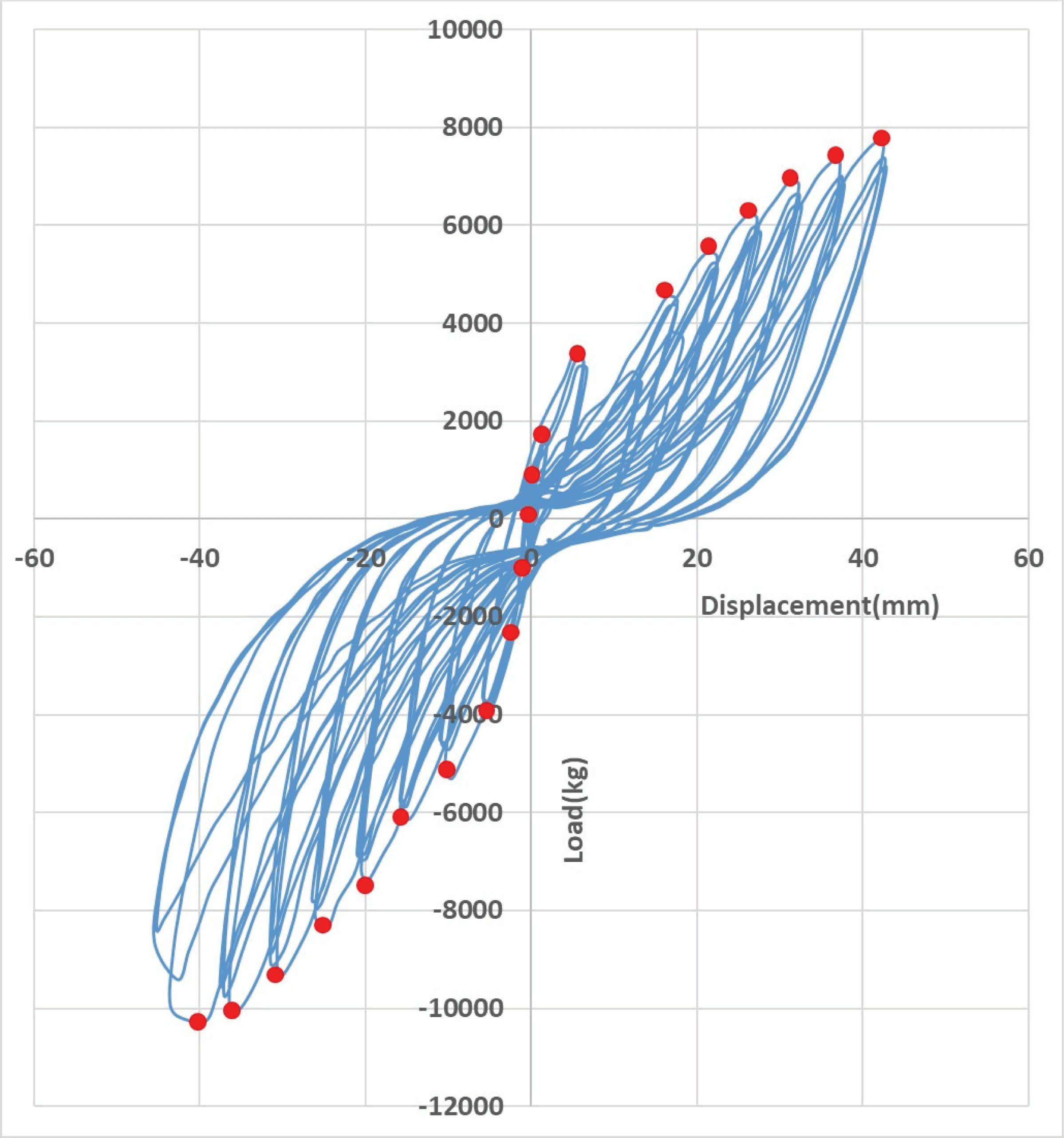
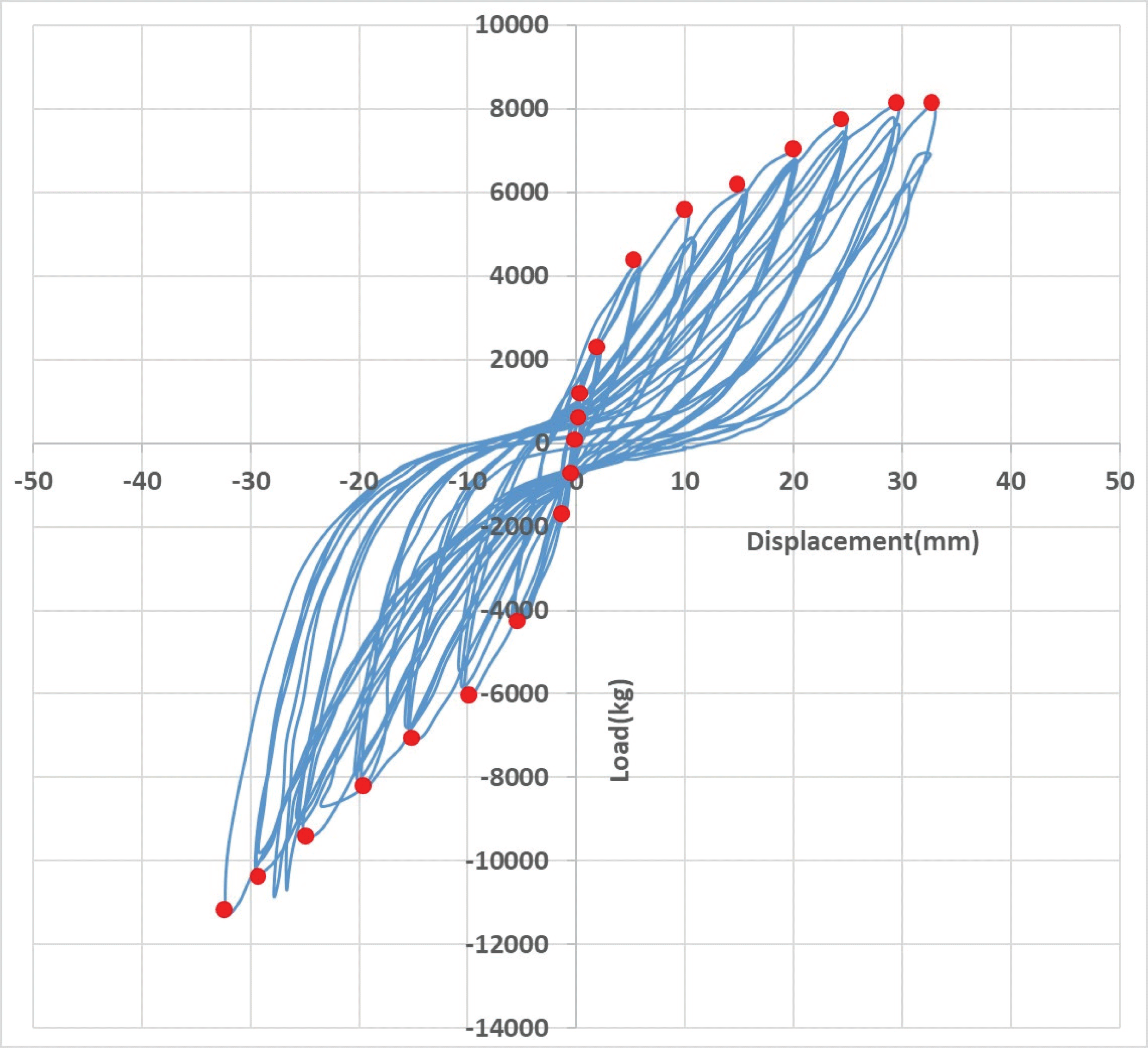
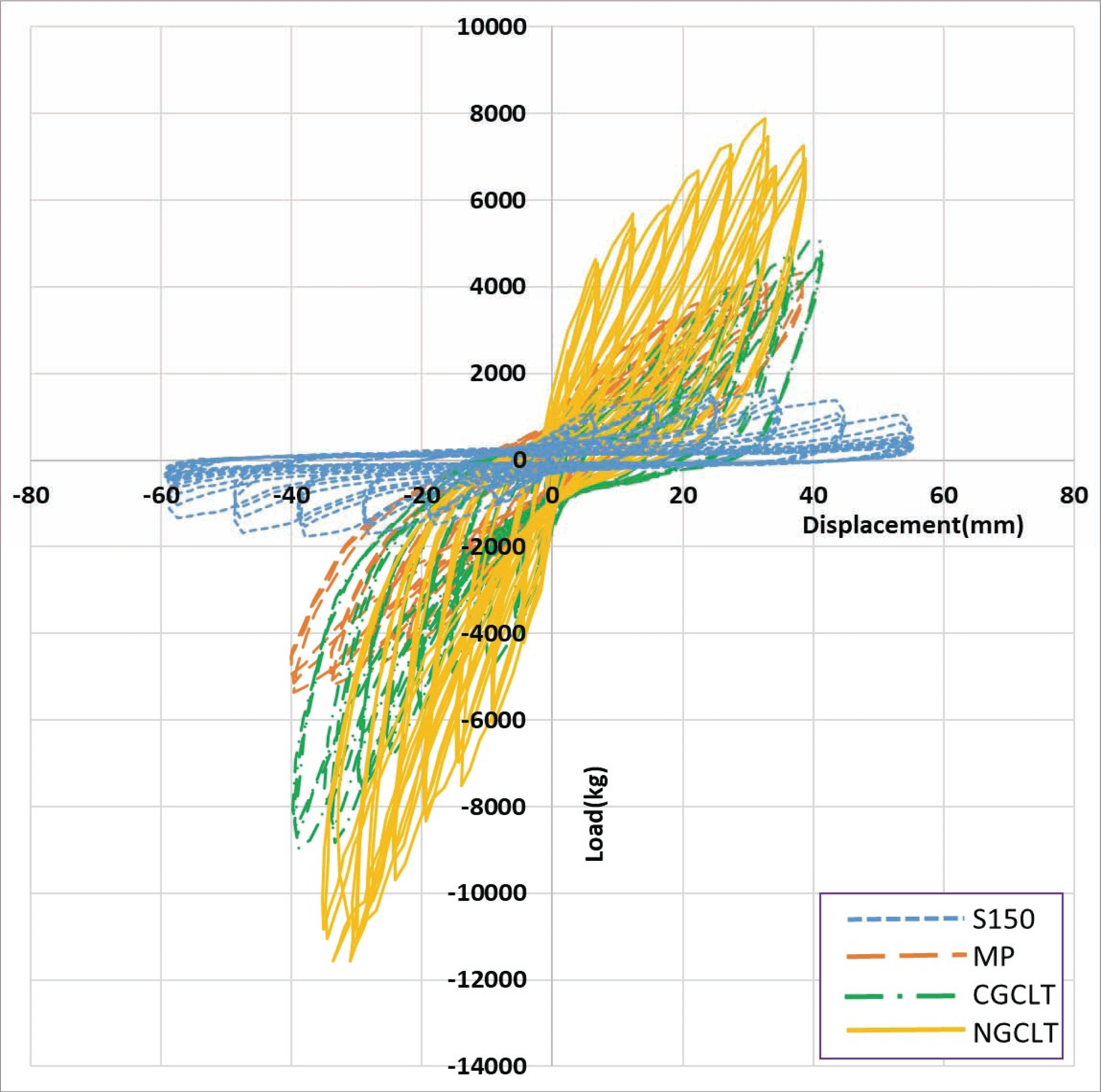
The load-displacement diagrams for S150, MP, CGCLT and NGCLT specimens are drawn together as shown in Fig. 13. From Fig. 13, it can say that NGCLT wall panel is strongest among the wall panels tested in this study, and S150 specimen showed the weakest shear strength. When comparing Fig. 8 with Fig. 9 and Fig. 10, it is known that S100 is stronger than S150 as a shear wall and MP is stronger than S100. After the tests, CGCLT and NGCLT specimens showed no damage in panel itself and failure was concentrated in the lower connection between CLT panel and sill plate, which was the same as the European and North American experiences that the nonlinear behaviour and the potential damage were localized to the hold-down and bracket connection areas only (Gagnon and Pirvu, 2011; Karacabeyli and Douglas, 2013).
The load-displacement diagram for S150 specimen given in Fig. 8 can be expressed as an envelop curve as shown in Fig. 14.
In Fig. 14, the initial slope of the envelop curve under 5,000 kg corresponds to the shear stiffness and the maximum load correspond to the shear strength. The envelop curve for MP specimen is given in Fig. 15, which shows higher stiffness and strength compared to those of S150 specimen given in Fig. 14.
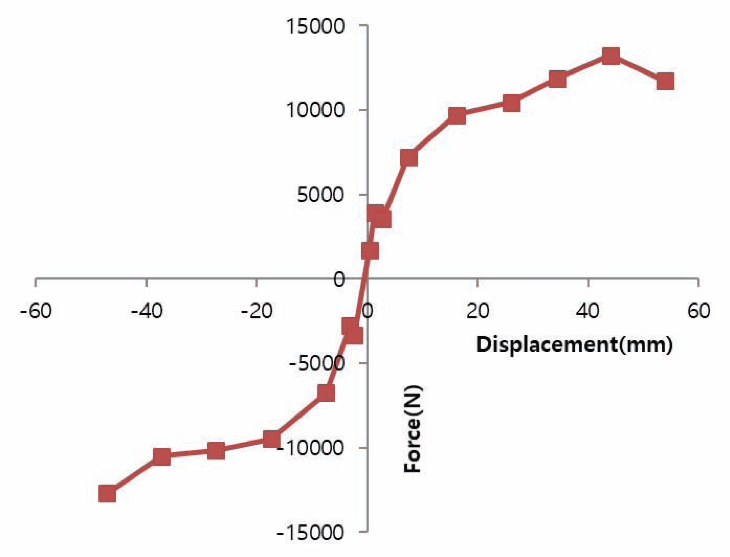
The envelop curve as shown in Fig. 14 and 15 can be drawn for each of the first, second and third cycle because each step of load function is composed of three cycles. The envelop curve for the first load cycle is called as the initial envelop curve and that for the third load cycle is called as the stabilized envelop curve. The envelop curve under the second load cycle usually represent the characteristics of the material under lateral loads.
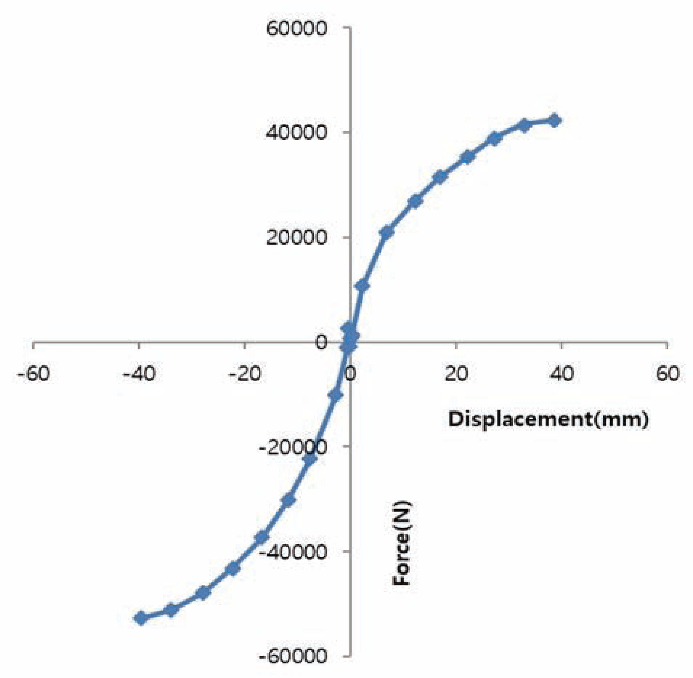
Fig. 16 shows all the envelop curves for NGCLT specimen including compression part, tension part and their average for each of three cycles.
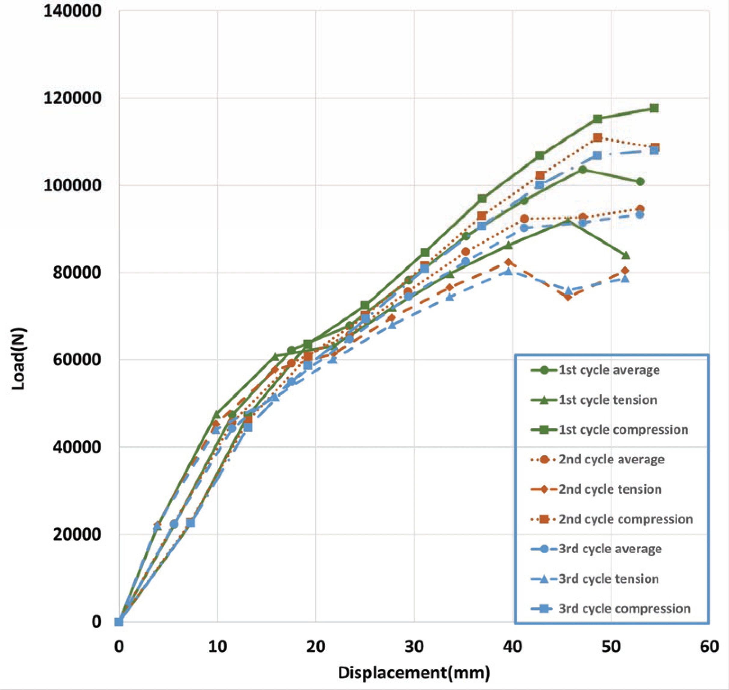
As shown in Fig. 16, the slope of the envelop curve is decreasing as the number of cycles increase. The envelop curves for all the tested specimens, which were similar to Fig. 14 and 15, were drawn to find shear stiffness and strength.
The apparent shear stiffness and the ultimate shear strength values for the specimens tested in this study are given in Table 1. As shown in Table 1, NGCLT specimen showed the highest shear strength(lateral-load resistance), CGCLT specimen was the second highest, MP specimen was the third, S100 specimen was the fourth, and S150 specimen showed the weakest lateralload resistance. The shear strength of the conventional light-frame wood shear wall increased about 50% when the space between nails decreased from 150 mm (S150) to 100 mm (S100) along the edge of panels. MP shear wall showed 2.7 times higher shear strength than S150 shear wall. CGCLT and NGCLT specimens showed 4.8 and 5.8 times higher shear strengths than that of S150 shear wall, respectively.
| Kind | Shear strength | Shear stiffness | ||
|---|---|---|---|---|
| (kN/m) | % | (N/mm) | % | |
| S150 | 6.15 | 100 | 122 | 100 |
| S100 | 9.71 | 158 | 192 | 157 |
| MP | 16.86 | 274 | 559 | 458 |
| CGCLT | 29.63 | 482 | 455 | 373 |
| NGCLT | 35.82 | 582 | 547 | 448 |
The apparent shear stiffness for CGCLT and NGCLT specimens were 455 N/mm and 547 N/mm, and the ultimate shear strength for CGCLT and NGCLT specimens were 29.63 kN/m and 35.82 kN/m, respectively. NGCLT showed higher shear stiffness and strength than CGCLT, which shows the effect of nails resisting the movement caused by the applied lateral loads. Therefore, it can say that nailing, when manufacturing CLT with square timber core and plywood cross bands, has effect of increasing the stiffness and strength of CLT as well as the advantage of saving time for manufacturing CLT products.
4. CONCLUSION
In this study, larch small square timbers were edge glued together to form core panel for CLT manufacturing, and 12 mm thick plywood panels were used as cross bands by covering the surface and the back of core panel. The plywood was attached to the surface and the back by two method including gluing and pressing, and gluing and nailing. In addition to CLT wall panels, conventional light frame wood shear walls and MP shear wall specimens were constructed to compare their lateral-load resistance. The conventional light frame wood shear wall specimen include two types such as nailing space of 150 mm and 100 mm along the edge of sheathing. In addition, another type of specimen was mid-ply shear wall in which wood-based panels are inserted in between two studs assembled face-to-face while the sheathing is attached on top of stud framing in the conventional shear wall specimen. All the wall panel specimens were tested under lateral loads in accordance with KS F 2154.
The lateral loads were applied as a quasi-static cyclic load function that is composed of nine loading steps in which each loading step is composed of three cyclic loads. As results of lateral-load resistance tests, loaddisplacement diagrams were obtained from which envelop curves were drawn. From the envelop curves, the apparent shear stiffness and the ultimate shear strength were calculated for each specimen type. Among the five specimen types, CLT specimens showed very high stiffness and strength compared to other types of specimens. In CLT specimens, NGCLT showed higher strength than CGCLT which state that nailing on plywood to attach plywood has effect of increasing the strength and stiffness. When compared to the shear strength of S150 shear wall, S100, MP, CGCLT and NGCLT specimens showed 1.5, 2.7, 4.8 and 5.8 times higher strength.


