1. INTRODUCTION
Since the early days of humanity, wood has been an important building material that meets the necessary structural needs using natural materials (Ramage et al., 2017). Because timber is an anisotropic material, it is difficult to obtain the desired cross-sectional dimensions of building elements (Akter and Bader, 2020; Kasal et al., 2003). Wood, a renewable material, is subjected to several processes after the tree is cut down in the forest until it can be used structurally (Asdrubali et al., 2015). These processes vary according to the location and purpose of the wood that will be used in the structure (Falk, 2009).
The density of wood is quite low compared to that of concrete and structural steel, and its bearing capacity is higher (Ansell, 2015; Dias et al., 2016; Yu et al., 2021). This relationship between density and load-bearing capacity provides different advantages for using wooden structural elements (Valdes et al., 2020). One of the most important factors is the earthquake effect, which is directly related to building mass (Dominguez-Santos et al., 2019; Pei et al., 2016). The low dead weight of wooden structures compared to reinforced concrete and steel constructions is advantageous in the event of an earthquake (Asizand, 2009). Another effect of density is that it positively affects the shape of the material. Considering these advantages, using wood as a structural element is attractive for architecture and engineering (Herzog et al., 2012).
Humans have used wood construction materials from trees in every field since the first ages (Ahmed and Arocho, 2020; Maier, 2021). After the tree is cut, it is separated from its branches and knots and turned into logs (Todoroki and Rönnqvist, 1999). Logs can be used structurally, and during the course of the process, solid wood can be obtained by drying or not drying the logs after they are cut (Huang et al., 2003). With the arrival of logs in this form, the more efficient use of wood-bearing features has enabled us to build structures with wood in terms of aesthetics and functionality (Ramage et al., 2017).
Laminated wood materials are used worldwide (bridge construction and wide-span systems, etc.; Nurdiah, 2016). Carrier system elements can be produced in desired dimensions and openings in wooden structural elements (Kurtoğlu and Zorlu, 1979; Yılmaz et al., 2022). The wooden boards used in the lamination process should have a homogeneous structure and should exhibit high-strength properties (Frangi et al., 2009). Their fire resistance is quite high compared with that of solid wooden structural elements (Schmid et al., 2019). The lightness of the carrier elements in wooden systems provides great convenience for production and assembly (Falk, 2005) because they can be dismantled and reused, and the parts in the system can be changed (Crowther, 1999).
Many external reinforcement methods are used with repair, steel, and fiber composite materials in building elements (Cha et al., 2022; Maras, 2021). The economic life of a structure can be increased by using composites to strengthen works of structural structural systems in the construction industry (Lee and Jang, 2023; Lee et al., 2019). The fiber composites, which have high tensile strength, exhibit ductile behavior by absorbing high energy and making large displacements under the effect of earthquakes (Kantarcı et al., 2023; Maras, 2021). In addition, press glue, which is a thermoplastic adhesive, is applied to wooden structures (Hadi et al., 2020). These adhesives help ensure bonding along the interface in the wood (Choi et al., 2021; Lestari et al., 2018). It improves the quality of the wooden product produced because it allows it to be used by removing its defects with a laminated process in wooden structures (Song and Kim, 2023; Yang et al., 2021).
Many studies have been conducted on strengthening building elements. It is aimed at producing high-strength and wide-span wooden beam elements as a result of the use of tensioned steel rope systems used to cross wide spans in wooden elements, as well as fiber-reinforced polymer (FRP) material, which is frequently used in reinforced concrete and masonry structures and is known to have a very high effect. Hybrid carbon fiber reinforced polymer (CFRP) and steel rope materials were used to reinforce the wooden beams. In this study, we aim to improve the mechanical properties of the beam element by combining these two methods in a laminated wooden beam element and to obtain a beam element with a higher span in smaller sections by reducing the shear and moment values, which will affect the beam element. Through this study, which will be performed by combining these two methods in a hybrid manner, better structural beam elements will be produced by improving the deficiencies of the methods themselves. Thus, the cross-sectional areas required for wide-span wooden structural elements are expected to be reduced.
2. MATERIALS and METHODS
Coniferous woods such as cedar, pine, cypress, and fir are used structurally, while tree species such as walnuts, beech, oak, and poplar are used in broad-leaved woods. Each tree type has distinct characteristics. Common to all species, the moisture content, knot condition, amount of fiber, and defects exhibit anisotropic behavior in terms of mechanical properties. Therefore, wood is classified according to its quality, particularly moisture content. This classification is used for measuring the dimensions of the obtained wood and determines its use as a support, carrier, or architectural element. Siberian pine was used as heat-treated wood material in this study. This material was heat treated according to the ThermoWood method at 212°C for 2 hours. Wooden beam elements were produced by sanding this process with different numbers. The solid wood plate used for the spruce wood was 1,200 mm × 3,500 mm and 30 mm thick.
CFRP composites are formed by combining different fiber layers and are the most commonly used FRP composite types in the field of reinforcement. Unidirectional and bidirectional composites with different physical and mechanical properties were obtained by arranging them in different directions in each layer. In contrast, the bidirectional plane fibers exhibit different strengths at every angle. A bidirectional carbon fiber cloth was used in this study. Unidirectional CFRP with 600 g/m2 area weight was used as CFRP. The mechanical properties of the CFRP are listed in Table 1.
| Variable | Thickness (mm) | Area weight (g/m2) | Tensile strength (MPa) | Modulus of elasticity (GPa) | Elongation at rupture (%) |
|---|---|---|---|---|---|
| CFRP | 0.7 | 600 | 4,137 | 242 | 1.5 |
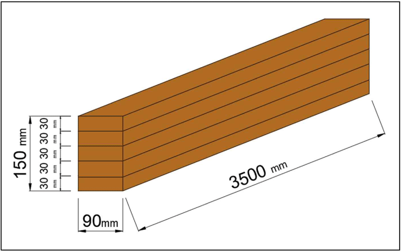
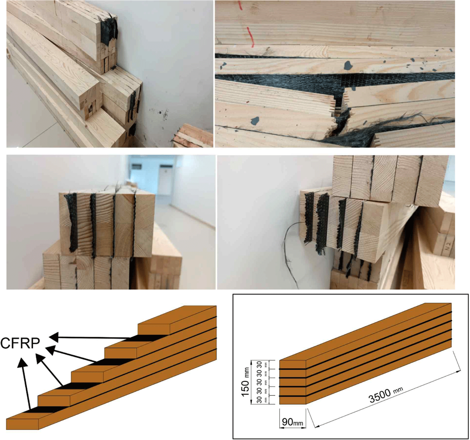
Wooden laminated elements are obtained by gluing two or more layers and joining the layers such that the fiber directions are parallel or perpendicular. If the produced wood laminate element is curved, the fiber directions of the layers must be applied in parallel. Different wood species and variable numbers of layers, sizes, shapes, and layer thicknesses can be applied to lamination. The purpose of using laminated wood is to eliminate the disadvantages of wood with anisotropic properties due to its nature. The laminated wood element is obtained by combining parts of the tree other than the defective areas using special glues of certain sizes so that the fiber directions are parallel. Thus, it is possible to produce wooden elements with better properties in all the desired dimensions. Any desired cross-sectional area can be obtained by the lamination process and joining of the wood pieces. Owing to this method, a prefabricated product is made. In this study, vinyl acetate polymer-adhesive wooden beams were produced by placing CFRP fabric on the interlayers before lamination (Fig. 1). This glue material has been used in both carbon fiber and lamination processes. This material is preferred because of its excellent adhesion strength, low viscosity, and ease of application. The technical specifications of the adhesive are listed in Table 2. The type of adhesive had a viscosity specification of 14,400 cps at 20°C with a density of 1.05 g/mL and class D3 water resistance.
| Chemical structure | Appearance | Density (g/mL) | Solid matter (%) | Viscosity (cps at 20°C) | pH | Glue line pressure (kg/cm2) | Water resistance class |
|---|---|---|---|---|---|---|---|
| Vinyl acetate polymer | White | 1.05 | 54 | 14,440 | 5–6 | 9–12 | D3 |
Laminated timber beams with steel-tension rods are typically used in large-span structures. Different types of construction are possible for large-span roof trusses and bridges. However, large dimensions are often required if this is done, which further increases the section forces (especially the bending moment) relative to their weight.
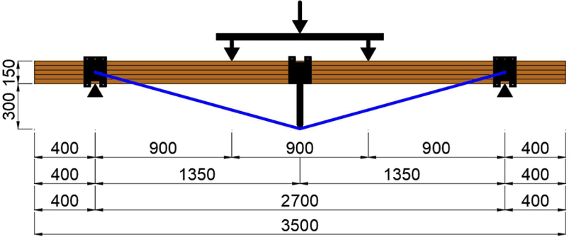
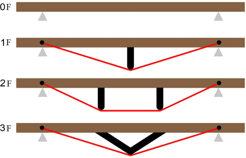
Another way to deal with large spans is to reduce the maximum bending moment of the beam. Adding one or more elastic intermediate supports, the static system transforms from a single-span beam to a double-span beam, or even a continuously supported beam. An intermediate support was placed, changing the behavior of the laminated timber using steel tension rods. The bending moment in the intermediate supports decreases the bending moment in the span. The intermediate support was elastic, and the tension rods were deformed by flexion under a load. Owing to the axial compression force, the length of the material decreased, and the tension rods lengthened. Considering the variations in the steel rope reinforcement method and the number of samples, three variations (two for each) were applied. The steel rope reinforcement method for specimen number 1 (1N) steel rope reinforcement method is illustrated in Fig. 2. The rope is brought into the V-form with the steel material placed in the middle of the wood in this method.
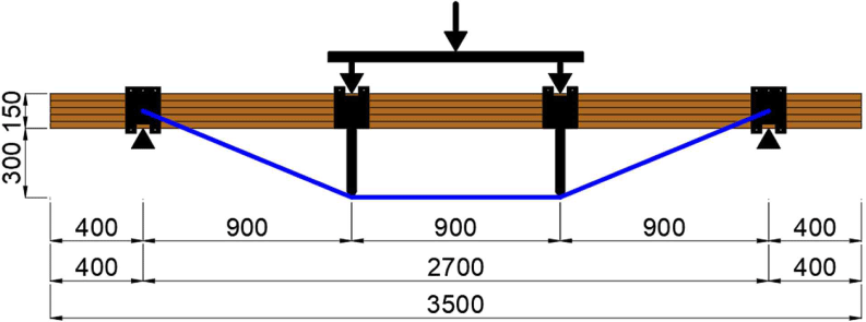
The steel rope reinforcement method for specimen 2 (2N) steel rope reinforcement method is illustrated in Fig. 3. In this method, a rope is formed into an inverted trapezoid with two different steel materials placed under the loading points.
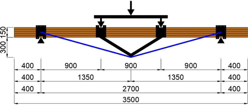
The steel rope reinforcement method for specimen number 3 (3N) is shown in Fig. 4. In this method, a V form with V-shaped steel material was placed at the lower part of the loading points.
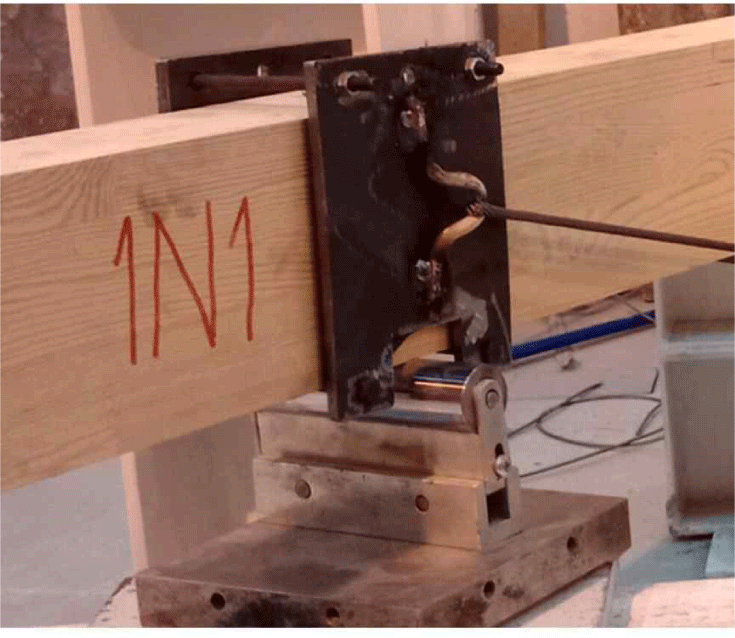
It was fixed by compression to avoid damage to the wood while fixing the ropes on the wood using 8 mm steel plates. The unit weights and breaking loads of the ropes are listed in Table 3. Simultaneously, these areas were cut into certain dimensions using a laser cutting method to prevent the steel elements from affecting the support and loading points. The planks were fixed to the wood surface by tightening them with mutual bolts and nuts (Fig. 5). A steel rope with a diameter of 6 mm was used in this study. Special clip elements and a key that can apply a tension force at the desired loads were used to fix the steel rope.
| Variable | Rope diameter (mm) | Unit weight (kg/m) | Tensile strength (MPa) | |
|---|---|---|---|---|
| Minimum breaking load (metric ton) | ||||
| Steel wire rope | 6 | 0.138 | 1,770 N/mm2 | 1,960 N/mm2 |
| 2.2 | 2.4 | |||
Laminated wood material is a structural element obtained by gluing wood lamellae, especially fibers, in parallel. It is a building element produced by joining solid timbers at the ends, side-by-side, and on top of each other to create large dimensions. It is necessary to arrange the structural elements parallel to the fiber direction. In this study, a carbon-fiber construction material was applied between the laminated layers and corner joints in wood using various methods (Fig. 6). Fig. 7 shows the laminated timber beams reinforced with both CFRP and steel ropes.
Wooden building elements can be produced on a large scale using the lamination process for wide-span wooden structures. In this study, different reinforcement methods were applied using steel ropes and FRP composites as laminated wood structural elements. These structural elements were tested using a loading system in accordance with TS EN 408 + A1 standards. Based on the findings obtained in this study, the aim was to reduce the cross-sectional area required for the required strength conditions of the structural laminated wood material in wide openings. The experimental setup was created in accordance with the regulation of TS 5497 EN 408, “Wood Structures - Structural Timber and Glued Laminated Timber - Determination of Some Physical and Mechanical Properties,” according to the measurement ratios given in Fig. 8(a). According to this regulation, a four-point loading system was used to examine the bending behavior of laminated wood elements. The distance between the two supports was 18 times greater than their heights. During the breaking of the beams, displacement measurements were made from three points, as shown in Fig. 8(b). While the deflection-measuring device numbered 1 (LVDT-1) was used by the device located on the loading mechanism, the deflection-measuring devices numbered 2 and 3 were also placed and loaded.

3. RESULTS and DISCUSSION
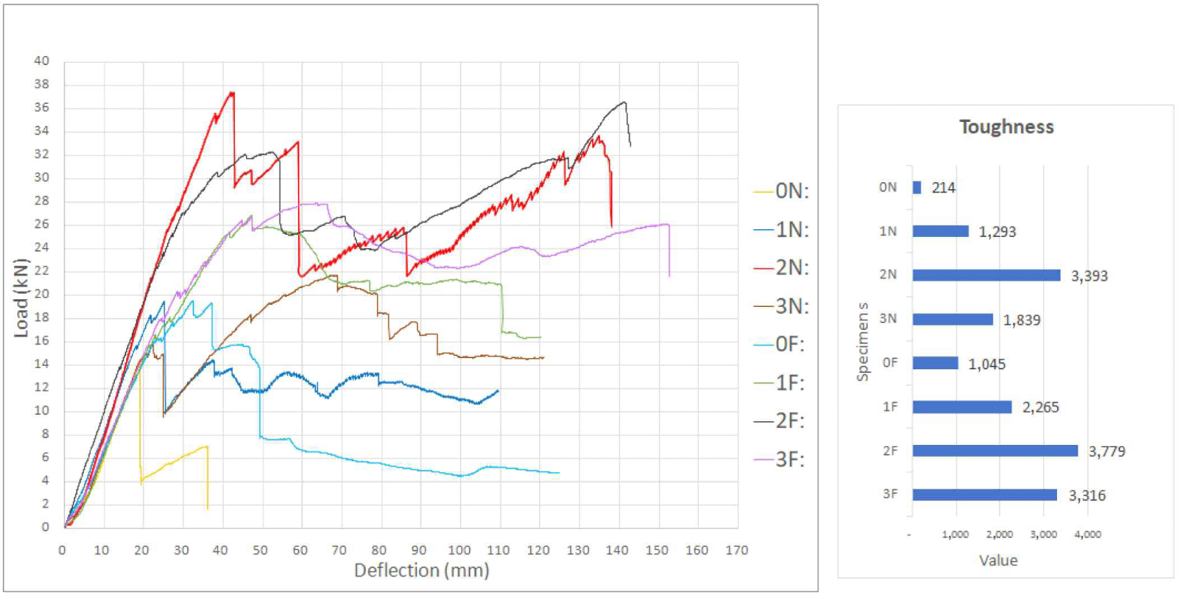
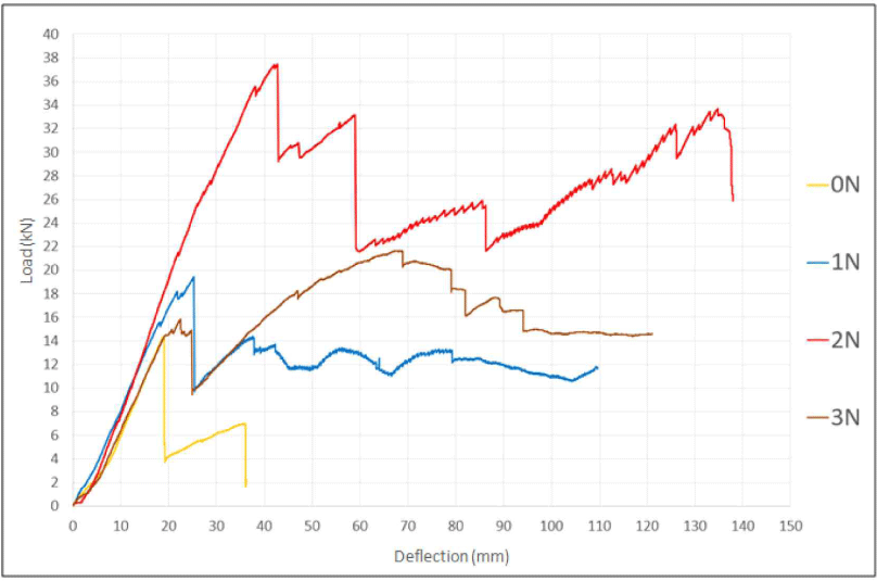
Reinforcement variations were created using steel ropes on laminated wooden beams. These wide-span beams are widely used in large-span roofs, trusses, and bridge systems. This study aimed to reduce the maximum bending moment of a reinforced beam. A load/deflection graph of the steel-rope-reinforced laminated beams with three different variations is shown in Fig. 9. The experimental findings showed that the normal laminated timber beam (0N) specimen had a maximum load of 14 kN and a deflection of 36 mm. Conversely, the highest increase in the values of the laminated beams reinforced with steel ropes was obtained with the specimen (2N) reinforcement, with a maximum load of 38 kN and a displacement of 137 mm. The structural behavior of laminated wood was investigated using steel tension rods with intermediate supports. The bending moment in the intermediate supports reduces the bending moment in the span. The intermediate support exhibited elastic behavior, and the studs and tension rods were deformed by flexion under a load (Rescalvo et al., 2017, 2018a). In this way, a load increase of 168% and a deflection increase of 275% compared to the reference sample were obtained. Because of the axial clamping force, the working length was shortened, and the tension rods were elongated (Raftery and Whelan, 2014). Owing to these deformations, the intermediate support was not vertically fixed as it was with normal supports at its two ends (Klasson et al., 2018; Valluzzi et al., 2007). Carbon fiber fabrics were evenly applied to the interlayers of the beams. Conversely, steel ropes are designed based on load points that affect the beams. In the specimens reinforced with steel ropes at different points on wooden beams, the shear force, which brings the beam to its bending capacity, remained low in regions with large shear gaps. These composites, which have a high tensile strength, exhibit ductile behavior by absorbing high energy and causing large displacements under the effects of earthquakes (Kim and Hong, 2011; Song et al., 2017).
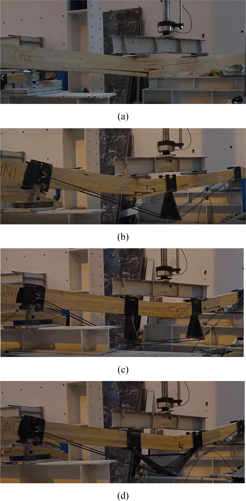
Typical failure modes and damage patterns of wooden beams under bending loads were determined and compared with the reference sample [Fig. 10(a)]. The steel-rope-reinforced samples showed a significant increase in the load-deformation curves. Cracks in the laminated wooden beams form in the junction areas of the solid panel, which are the weakest. In the normally laminated (0N) timber beam specimen, cracks progressed rapidly from the lowest to the upper layers. Because the steel rope absorbed the load of the steel-rope-reinforced samples, the formation of cracks and their transfer to the upper layers were prevented. In this way, while obtaining more load and deflection, significant increases in energy absorption were also achieved. It is stated that it is possible to partially restore the bending capacity of damaged wooden beams by strengthening them (Corradi et al., 2021; Gribanov et al., 2020). When a steel rope reinforcement specimen of 1N was examined under the influence of the four-point loading mechanism, the cracks progressed to the upper layers, starting from the points where the load was applied. Although the steel material used in the specimen 1N wire rope strengthening method in the middle of the wooden beam prevented the formation of cracks under the effect of the load, it was less effective than the other methods [Fig. 10(b)]. Specimen 2N wire rope reinforcement contributed much more than specimen 1N reinforcement by placing the steel elements just below the point where the loads were applied to the wood [Fig. 10(c)]. In the 3N sample steel rope-reinforced beam [Fig. 10(d)], steel elements placed directly below the loading points have a better effect than reinforcement sample 1N, but this is more difficult compared to reinforcement sample 2N; low strength was obtained. Similarly, as the flexural strength, bond length, and bond width of reinforced wooden beams increase, the ultimate load-carrying capacity also improves significantly (Vahedian et al., 2019). When we examined the damaged areas, it was determined that the position of the steel elements had a significant effect on the spread of the beam at two different points in reinforcement specimen 2N. However, the formation of the crack zone occurred at a single point in reinforcement specimens 1N and 3N. The use of reinforced laminated wood beams has made it possible to obtain a structural material with higher quality control and less variation in final loads, thereby reducing the timber defects in wood-based composite materials (Cai and Ross, 2010; Philbin and Gordon, 2006). Similarly, it has been shown that increasing the stress reinforcement ratio can change the failure mode from bending to shear with a reduced maximum midspan deflection (de la Rosa García et al., 2013). The application of plates in the external reinforcement significantly increases the shear strength of the beam compared to its normal shear capacity (Jasieńko and Nowak, 2014).
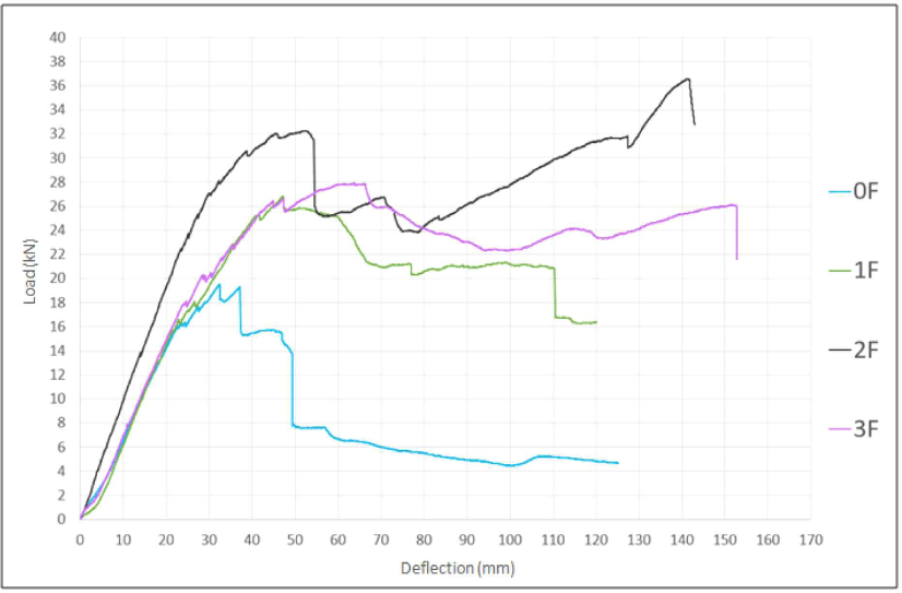
The structural behavior of wooden beams reinforced with CFRP and steel ropes under four-point loading was investigated. Fig. 11 shows the load/deflection graphs of the steel rope- and CFRP-reinforced laminated beams with three different variations. The experimental results demonstrated that the reference laminated timber beam specimen (0F) had a maximum load of 19 kN and a displacement of 125 mm. Specimen (1F) timber beam had a maximum load of 27 kN and a deflection of 120 mm. Wooden beams reinforced with FRP composites significantly increase the ductility of beams with an increasing moment capacity (Rescalvo et al., 2018b; Yang et al., 2013). The 3F beam reinforced with CFRP and steel ropes exhibited a maximum load of 28 kN and displacement of 152 mm. It was shown that beams reinforced with CFRP composites limit wood defects and prevent severe damage (Khelifa et al., 2015; Yang et al., 2014). The highest increase in the values of the laminated beams reinforced with steel rope and CFRP was determined with reinforcement number 2 (2F), with a maximum load of 32 kN and a displacement of 143 mm. Thus, a load increase of 92% and displacement increase of 14% were obtained compared with the reference sample. In many studies, reinforcing wooden beams with FRP layers (more than three layers) reduced efficiency and increased costs (İşleyen et al., 2021; Ling et al., 2020; Rescalvo et al., 2018a). It was observed that the CFRP-reinforced wooden beams increased the load-bearing capacity by more than 50% and exhibited ductile behavior. Nowak (2007) investigated the load capacities of solid wood beams reinforced with CFRP strips and noted that the greatest increase (approximately 80%) was obtained in the beam regions where the strips were placed. Similarly, Corradi et al. (2017). The use of regional reinforcement CFRP plates only in weak areas also showed mechanical properties above the old bearing capacity where it was efficient.
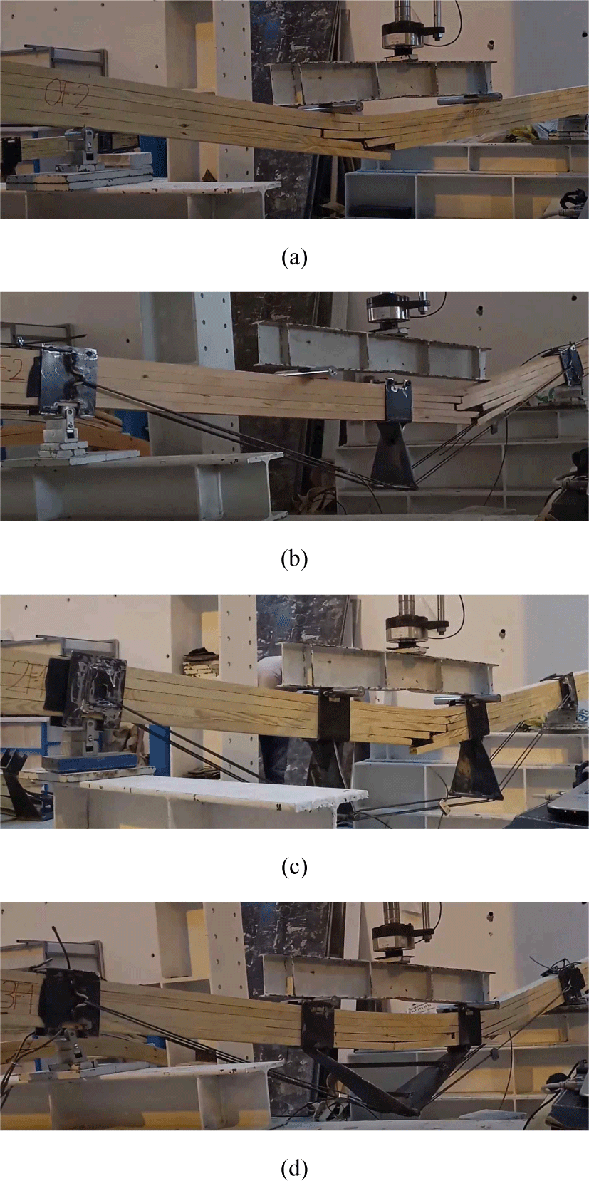
Damage to unreinforced wooden beams typically occurs in the lower part of a section close to the loading point. Subsequently, the cracks expanded further and gradually progressed as the shear cracks reached the loading point. The crack propagation process in wooden beams varies depending on the section height and crack opening surface (de Moura et al., 2006, 2008). However, the fabrics placed between the layers with CFRP prevented crack development and provided a significant interlayer connection. The fiber polymer composites did not cause damage and contributed significantly to the load-carrying capacity of the wooden beams (Saad and Lengyel, 2022). An increase in displacement was observed in the reference CFRP wood sample (0F) [Fig. 12(a)] compared with the normal wood sample (0N). The CFRP material placed between the layers increased the strength and deformation by satisfying the tensile forces in the lower parts of the beam. These composites with high toughness did not break, contributing significantly to the structural element by exhibiting ductile behavior under bending loads (Ghanbari-Ghazijahani et al., 2020; Vahedian et al., 2019; Wei et al., 2022). When steel rope systems were used, a greater increase was observed compared with steel reinforcements in normal wooden beams. The most significant factor observed was that the transition of cracks to the upper layers was greatly reduced; by providing significant adherence between the laminated plates, severe damage did not occur, and the bearing capacity and ductility of wooden elements reinforced with steel ropes increased significantly. In similar studies, it has been concluded that the use of steel ropes contributes significantly to this behavior and significantly improves their mechanical properties (Borri and Corradi, 2011; Bulleit et al., 1989).
The toughness is an important parameter that measures the energy absorption capacity of all columns until failure under an axial load (Munch et al., 2008; Soderholm, 2010). In this study, the toughness capacities of hybrid-reinforced laminated timber beams under axial loading were compared. The load-deformation graph and toughness values of all the samples were determined. Thus, a load increase of 168% and displacement increase of 275% compared with the reference sample were obtained. In addition, considering the toughness, a value of 214 was obtained in the reference sample, and a value of 3,393 in the specimen 2N reinforcement, an increase of 1,486% was obtained. It was observed that laminated timber beams reinforced with CFRP prevent local buckling and provide a significant increase in ductility, axial load carrying, and toughness capacities. In addition, studies have shown that increasing the fiber ratio increases the ductility and toughness of wood elements (Borrega and Kärenlampi, 2008; Fragiacomo et al., 2011).
Compared with the reference sample, a load increase of 92% and a displacement increase of 14% were obtained. In addition, considering the toughness, a value of 1,045 was obtained for the reference sample, and a value of 3,779 was obtained for the strengthened specimen 2F; an increase of 262% was obtained. These results indicate that reinforced wooden beams increase their toughness and absorb more energy (Abdulla et al., 2020; Sumardi et al., 2022). It was revealed that when the fibrous polymer composite ratio increased, the fracture and impact energies, toughness, and ductility increased. It is generally known that the bond strength between wood and FRP is lower than that between woods. In this case, by applying a composite reinforcement method to wooden beams, the steel ropes continued to carry loads, showing high toughness and energy absorption capacity, even if the CFRP lost a certain load effect (Fig. 13).
4. CONCLUSIONS
This study discusses the structural performance of wood beams reinforced with hybrid reinforcements. In this study, high ductility was developed to strengthen wooden beams using hybrid-reinforced composite methods.
In this study, environmentally friendly and sustainable wooden structural beam elements that can be used in the passage of wide spans of buildings were designed.
In addition, the mechanical properties of the beam elements were improved by combining the hybrid strengthening method with a laminated wooden beam element.
In the specimens reinforced with steel ropes at different points on wooden beams, the shear force, which brings the beam to its bending capacity, remained at a low level in regions with large shear gaps.
-
- Cracks in the laminated wooden beams were formed in the junction areas of the solid panel, which were the weakest areas.
-
- CFRP-reinforced wooden beams increased load-bearing capacity by more than 50% and exhibited ductile behavior.
-
- The CFRP material placed between the layers increased the strength and deformation values by satisfying the tensile forces in the lower parts of the beam.
-
- Carbon fabrics placed between the layers of CFRP prevent the development of cracks, do not spoil aesthetics, and will be able to reduce the effects of earthquake forces.


