1. INTRODUCTION
Nowadays, people are getting more and more interested in global weather change issues and residential environment, which, in turn, resulted in the increased interest in trees and wood. Wood is one of the major renewable natural and eco-friendly materials and wooden buildings can store carbon in their body for the lifetime of the building, which may be helpful to delay the weather change by reducing CO2 concentration in the air. To construct wooden buildings as strong as possible, one of the most essential structural components is joint or attachment between wood members because stiff and powerful attachments are the key part of the whole building to ensure safety and durability.
Dowel, nail, bolt, and/or lag screw are widely used to connect between various wood members. Studies on the structural performance of dowel-type fasteners such as nails and screws were started recently in Korea. Ahn et al. (2021) performed the withdrawal tests for the single self-tapping screw joint with three kinds of wood products including CLT and compared the results of tests with the predictions obtained by the estimation equation given in NDS (2018). Kim (1979) measured the static resistance of nail in three directions of Japanese cedar and Korean red pine, and reported that the withdrawal-resistance in the cross- sectional surface is weakest for both species. Kim also reported that the withdrawal-resistance of tangential direction is significantly higher than that of radial direction in case of Japanese cedar while there is almost no difference between radial and tangential direction in case of Korean red pine because of their structural features. Cha (2011) has studied on predicting the withdrawal load of wood screws in domestic wood depending on screw diameter, penetration depth and specific gravity of wood. Cha (2012) has performed research on the withdrawal strength of wood screws in domestic wood depending on the shear strength with different growth ring orientation. Oh (2013) measured the withdrawal and lateral resistance of nail joints composed of dimension lumber and OSB, which is commonly used in light-frame wood construction, and reported that withdrawal-resistance is proportional to the density of lumber. Cha (2016) studied the effect of diameter and pre-hole clearance for wooden dowel installed in domestic wood under the withdrawal loads. Korean Building Code (KBC, 2016) published by Architectural Institute of Korea (AIK) includes the withdrawal design values for lag screws obtained from National Design Specification (NDS, 2018) without verification through tests.
Even though researches on the small size dowel-type fasteners such as nails and screws have been performed recently in Korea, researches on the structural behaviour of the large size dowel-type fasteners such as bolt or lag screw which are usually used for heavy timber construction is insufficient. Lag screw is one of the most popular fasteners commonly used in modern style timber structure to connect between wood members or between wood member and steel connector. To install the lag screw, the lead-hole should be pre-drilled to prevent wood cleavage during the installation of the lag screw. Korea Building Code (KBC, 2016) states that the lead-hole for the shank portion of the lag screw shall have the diameter equal to the shank diameter, and that for the threaded portion of lag screw shall have the diameter corresponding to 70% to 80% of the shank diameter for wood with specific gravity (G) > 0.6, 60% to 70% for wood with 0.5 < G < 0.6, and 40% to 60% for wood with G < 0.5, and the depth equal to the length of the threaded portion. The larger percentile in each range shall apply to lag screws of greater diameter.
However, it may be difficult to understand how to install lag screws in accordance with KBC and to make a lead-hole with two different diameters for one lag screw in the construction site. To overcome this problem by finding the way to install the lag screw easily, the effect of one lead-hole size on the withdrawal resistance of lag screw was studied in this study. And also the effect of species, grain direction, screw size, lead-hole size and screw type (lag screw, tapping screw, Sherpa screw) on the withdrawal resistance were studied, and the results of the tests were compared with the values calculated by using the equation given in NDS (2018) and KBC (2016). The tapping and the Sherpa screw have the advantage that they can be installed without pre-drilling even though they are more expensive than the lag screw.
2. MATERIALS and METHODS
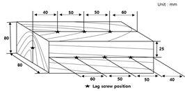
Sawn and dried lumber of domestic larch and imported spruce were used in this study. The moisture content and the density of wood specimen measured in accordance with KS F 2199 and KS F 2198, respectively. The moisture content was ranged between 11%~12%, and the density was 560 kg/m3 for larch and 440 kg/m3 for spruce. The size of wood specimen was 80 mm (width) x 80 mm (height) x 200 mm (length) as shown in Fig. 1 and the locations of lag screw installation are shown in Fig. 1.
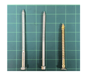
Three types of fasteners (lag screw, tapping screw and Sherpa screw) as shown in Fig. 2 were used in this study. The diameter of the fasteners used in this study were 9.46 mm, 7.79 mm and 6.27 mm for the lag screw, 6.3 mm for the tapping screw, and 8.0 mm for Sherpa screw. The total length of the fasteners were 130.3 mm for 9.46 mm and 7.79 mm diameter lag screws, 102.3 mm for 6.27 mm diameter lag screw, 126.0 mm for the tapping screw and 99.3 mm for Sherpa screw. When measuring the penetration depth for the threaded portion of the fasteners in the main member, the length of the tapered tip was not included. Detailed dimension of the fasteners used in this study is given in Table 1.
In this study, specimen symbols are specified as given in Fig. 3.
To install the lag screw, pre-drilling was applied to prevent cleavage in the radial and tangential direction of wood. Three different lead-hole sizes, such as 68.7%, 70.8% and 74.0% of shank diameter (9.46 mm) of the lag screw, were applied to determine their effect on the withdrawal resistance of the lag screw installed in larch specimen, and their details are given in Table 2.
| Specimen symbol | Lead-hole diameter (mm) |
Percentage* (%) |
Species |
|---|---|---|---|
| 9.46LL-6.5 | 6.5 | 68.7 | larch |
| 9.46LL-6.7 | 6.7 | 70.8 | |
| 9.46LL-7.0 | 7.0 | 74.0 |
To evaluate the effect of lag screw diameter, lag screws having three different shank diameter of 9.46 mm, 7.79 mm and 6.27 mm were used. Larch and spruce were used as the main member to study the effect of species and grain direction (radial, tangential, longitudinal (cross-section)). Details of the specimens for lag screw are given in Table 3. In Table 3, the lag screw having diameter of 7.79 mm was tested on three different surfaces (T, R, C) to evaluate the effect of grain direction while the other lag screws was tested on two different surfaces (S, C) without separating T and R because it may be very difficult to distinguish between T and R at the actual construction site. Actually, the withdrawal resistance for the screw-type fastener in NDS (2018) and KBC (2016) is given for the side grain (mixed grain of T and R) without separating T and R.
To evaluate the effect of fastener type, the tapping screw having the diameter of 6.3 mm and Sherpa screw having the diameter of 8.0 mm were used. Tapping screw and Sherpa screw are usually installed without the pre-drilled lead-hole. The tapping and Sherpa screws were tested on larch, and the effect of the grain direction (S, C) was evaluated. Details of the specimens for the tapping and Sherpa screws are given in Table 4.
| Specimen symbol | Fastener diameter (mm) | Species | Grain Direction |
|---|---|---|---|
| 6.3TL-S 6.3TL-C |
6.3 | Larch | S (T/R) C |
| 8.0SL-S 8.0SL-C |
8.0 | Larch | S (T/R) C |
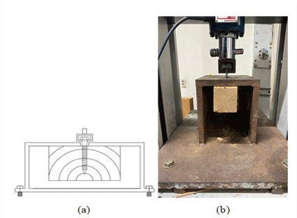
The withdrawal-resistance tests were performed in accordance with KS F ISO 9087. To measure the withdrawal resistance of the screw-type fasteners under pulling load, the testing arrangement as shown in Fig. 4 was employed.
During the withdrawal test, the pulling load was applied at a constant speed so that the screw be pulled out within 1~2 minutes after starting the test, and the maximum load was recorded with the accuracy of ±1%. For the whole tests, the number of replication was 10, and 5 percentile (5 % lower exclusion limit) was calculated based on the assumption of normal distribution of the test results, and the allowable withdrawal load was calculated by dividing the 5 percentile by the safety factor of 2.0.
The withdrawal strength was calculated by dividing the maximum withdrawal load by the penetration depth of the fastener as given in equation (1).
Where,
σw: Maximum strength (N/mm)
Fmax: Maximum withdrawal load (N)
L: Penetration depth (mm)
3. RESULTS and DISCUSSION
The examples of the load-displacement diagrams for 9.46LL-6.5, 9.46LL-6.7 and 9.46LL-7.0 specimens are shown together in Fig. 5.
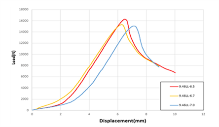
As given in Fig. 5, the specimen with the lead-hole size of 6.5 mm (9.46LL-6.5) was strongest among the three lead-hole sizes applied in this study while the specimen with the lead-hole size of 7.0 mm (9.46LL- 7.0) was the weakest. For the specimens with smaller lead-holes (9.46LL-6.5 and 9.46LL-6.7), large amount of rotational force was required during the installation of the lag screw which caused excessive stress in the neck of the lag screw and resulted in the breakage of the neck for some specimens during the test. Table 5 shows the measurements of withdrawal resistance depending on the lead-hole size.
| Specimen symbol | Fmax (N) | σw (N/mm) |
|---|---|---|
| 9.46LL-6.5 9.46LL-6.7 9.46LL-7.0 |
19,184 18,510 18,172 |
270.2 260.7 255.9 |
As shown in Fig. 5 and Table 5, the difference of the withdrawal resistance among the three types of lead-hole size specimens was not great and it was observed that large amount of rotational force was required to install lag screws for the specimens with smaller lead-hole sizes (6.5 mm and 6.7 mm), which caused the breakage of the neck during the test for some specimens. To avoid the large rotational forces that might cause the breakage of the neck, the lead-hole size corresponding to 74% of the screw shank diameter was employed through the rest of the tests in this study. Even though the lead-hole size corresponding to 60~70% of the screw shank be recommended for the wood member having the specific gravity between 0.5 and 0.6 in KBC (2016), it was observed in this study that the lead-hole size corresponding to around 70% or less of the screw shank caused the excessive stress in the screw neck during the installation that may cause the breakage in the screw neck. Therefore, the recommended lead-hole size as given in KBC (2016) shall be reconsidered to avoid damage in the screw neck under loads.
The test results for the effect of grain direction on the withdrawal resistance of the lag screw is given in Table 6.
| Specimen symbol | σw (N/mm) |
5 percentile (N/mm) |
W* (N/mm) |
|---|---|---|---|
| 7.79LL-T 7.79LL-R 7.79LL-C |
177.6 196.9 126.1 |
156.0 161.0 83.5 |
78.0 80.5 41.7 |
| 7.79LS-T 7.79LS-R 7.79LS-C |
119.4 124.7 86.6 |
83.6 87.2 55.0 |
41.8 43.6 27.5 |
As shown in Table 6, the lag screw installed on the radial surface showed the highest withdrawal resistance even though the difference from those installed on the tangential surface is very small (less than 5%), while the lag screw installed on the cross section showed the lowest withdrawal resistance. From the fact that there is no significant difference between the withdrawal resistances of the lag screws installed on the tangential and radial surfaces, it was considered that the withdrawal test of the lag screw can be performed without distinguishing the tangential and radial directions. Therefore, the rest of the withdrawal tests in this study were performed for the grain directions S (mixed grain of T and R) and C. Actually, it is almost impossible to distinguish between the tangential and radial directions when installing the lag screws in the construction sites, and the design or allowable withdrawal load are given based on the side grain (mixed grain of T and R) in the Building Codes including NDS (2018) and KBC (2016).
The results of the withdrawal resistance tests for the lag screws used in this study can be summarized as given in Table 7.
As given in Table 7, the allowable withdrawal load (W) of lag screws installed in larch showed higher withdrawal resistance than those installed in spruce as expected because larch has higher density (560 kg/m3) than spruce (440 kg/m3). And the withdrawal resistance of the lag screws installed on the side grain was higher than those installed on the cross section. As the screw diameter increased from 6.27 mm to 9.46 mm, the withdrawal resistance was almost proportionally increased regardless of the grain direction.
To compare the results of this study with the withdrawal resistance given in NDS (2018), Table 8 was calculated by using Equation (2) which was obtained from the equation given in NDS (2018) for withdrawal design value of the lag screw installed on the side grain by converting the units from US Conventional system to IS system.
| Specific Gravity (G) | Lag Screw Diameter, D (mm) | ||
|---|---|---|---|
| 6.27 | 7.79 | 9.46 | |
| 0.56 | 46.2 | 54.3 | 62.8 |
| 0.44 | 32.1 | 37.8 | 43.8 |
Where,
W: Withdrawal design value (N/mm)
G: Specific gravity of wood member
D: Shank diameter of the lag screw (mm)
In KBC (2016), the equation to calculate the withdrawal resistance of lag screw is given as Equation (3), which gives around 1/10 of the values obtained by Equation (2). And also Equation (3) calculate different values from the table given as the allowable withdrawal load for lag screw in KBC (2016). Therefore, it shall be considered that Equation (3) given in KBC (2016) be changed to Equation (2) in the future.
Where, G and D indicate the same meaning as Equation (2)
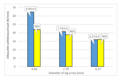
Fig. 6 and 7 show the comparison between the withdrawal resistances of lag screws obtained as the result of this study and those given in Table 8 obtained from the Equation (2) with the main member species of larch and spruce, respectively.
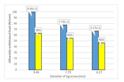
As shown in Fig. 6 and 7, the withdrawal resistances of the lag screws obtained from this study are higher than those obtained from the equation given in NDS (2018) except the lag screw with the diameter of 6.27 mm installed in spruce for which the withdrawal resistance is similar to the value given in NDS (2018). Therefore, it is known that one lead-hole size instead of two different lead-hole sizes for one lag screw is sufficient to secure the allowable withdrawal load given in the Building Code by considering that the allowable withdrawal load measured in this study for the lag screws with one lead-hole size be greater than those given in KBC (2016) which is similar to the values given in NDS (2018).
The results of withdrawal tests with the tapping screws and Sherpa screws are given in Table 9 and the comparisons of the withdrawal resistance depending on the screw type are given in Fig. 8 and 9.
| Specimen symbol | σw (N/mm) | 5 Percentile (N/mm) |
W (N/mm) |
Percentage of Wc /Ws (%) |
|---|---|---|---|---|
| 6.3TL-S 6.3TL-C |
264.7 171.4 |
215.5 128.8 |
107.8 64.4 |
59.7 |
| 8.0SL-S 8.0SL-C |
276.6 173.0 |
216.9 113.6 |
108.5 56.8 |
52.4 |
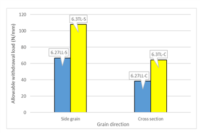
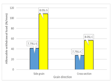
As given in Table 9, the withdrawal resistance of the tapping screw was similar to that of Sherpa screw even though the diameter of Sherpa screw is greater than that of the tapping screw. Although the allowable withdrawal load for both the tapping and Sherpa screws were similar, the maximum withdrawal load for Sherpa screw was higher than that of the tapping screw because the length of threaded portion of Sherpa screw was longer than that of the tapping screw.
As it is shown in Fig. 8 and 9 and by comparing Table 7 and 9, the withdrawal resistances of the tapping and Sherpa screws were around 1.6 and 1.4 times higher, respectively, than those of the lag screws having similar diameter regardless of the grain direction. Even though it is not clear why such a differences in the withdrawal resistance depending on the screw type be resulted, it might be caused by the differences in the space between threads and the thread length depending on the screw type.
The withdrawal resistance of the lag screw installed on the cross section (end grain) can be obtained by multiplying the adjustment factor (0.75) to that of the lag screw installed on the side grain as given in NDS (2018) and KBC (2016). However, Table 7 and 9 show that the withdrawal resistance of the lag screw installed in the end grain may be around 55% to 65% of that of the lag screw installed in the side grain, which is much less than 75%. Therefore, it may be needed to study more about the possibility of changing the adjustment factor given in KBC (2016) for the lag screw installed in the end grain even though it is not common to design the lag screws installed on the end grain under withdrawal load.
4. CONCLUSION
In this study, the withdrawal resistances of the screw-type fasteners including domestic lag screws (diameters of 9.46 mm, 7.79 mm and 6.27 mm), domestic tapping screws (diameter 6.3 mm) and imported Sherpa screws (diameter 8.0 mm) were tested to evaluate the effects of lead-hole size, grain direction, species of main member and screw diameter. Sawn and dried lumber of domestic larch and imported spruce were used as main members and the withdrawal tests were performed in accordance with KS F ISO 9087 for tangential, radial and longitudinal directions.
Through the withdrawal tests with the specimens having different lead-hole sizes, it was concluded that the lead-hole corresponding to 74% of the shank diameter of the lag screw was appropriate for this study because the smaller lead-holes required higher rotational force for installation which may cause damage in the screw neck even though there was no significant difference in the withdrawal resistance depending on the lead-hole sizes applied in this study. The withdrawal resistances in the grain direction of tangential and radial were higher than that in the longitudinal direction but similar to each other. Therefore, the withdrawal tests were performed in the direction of side grain, which is mixed of tangential and radial, and end grain (longitudinal direction) without distinguishing between tangential and radial direction.
As the lag screw diameter increased from 6.27 mm to 9.46 mm, the withdrawal-resistance increased almost proportionally and were greater than those currently given in NDS and KBC. The withdrawal resistances of the tapping and Sherpa screws were almost 1.6 and 1.4 times higher, respectively, than those of the lag screws having similar diameter of 6.27 mm and 7.79 mm.


