1. INTRODUCTION
Wood is a green material due to the lower energy to become final products (Rafiei and Adeli, 2016) and the carbon storage effect of harvested wood products (HWPs) was globally recognized (Ji et al., 2016). Engineered Wood Products (EWPs) such as cross-laminated timber (CLT) help make a more efficient use of low-value and small-diameter trees (Forest Products Lab, 2010; Woodall, 2011). The EWPs are manufactured by the laminas to achieve targeted engineering properties, such as strength (Mallo and Espinoza, 2015).
Because a layer in CLT is orthogonal to the principal axis of adjacent layers, a load not only is transferred in one direction, but to all side (FPInnovations, 2011). This feature leads to large-scale components and enables fast construction (Chen, 2011). Researchers (Sikora et al., 2016; Li, 2017; Wang et al., 2017) investigated the structural properties of CLT and standards for CLT (ANSI/APA, 2012; EN 16351, 2014; FPInnovations, 2011) were recently published. They provide the technical information relating to CLT products which were manufactured by a gluing process. However, a lot of investment is required for manufacturing CLT by adhesives, since a unique manufacturing facility should be provided for adhering the laminas. If the laminas are connected with nails, it is possible to make CLT with a small initial investment. Only a nail-gun and nails are required for making them. The nail-gun and nails are highly commercialized and most timber construction companies or manufacturers have them. The development and improvement of connecting technologies using nails will also extend the possibilities of wood-based construction.
In order to improve the utilization of the domestic wood, several researchers investigated the strength properties of domestic CLT. Kim et al. (2013) and Park et al. (2017) evaluated the shear strength of CLT for finding out the optimum adhesive condition for domestic species. Oh et al. (2015) developed lamina property- based model for predicting the compressive strength of CLT. Oh et al. (2017) investigated the shear behavior of CLT wall consisting of small panels to find out the more efficient use of small size CLT panel due to the domestic wood industry condition. It is impossible to produce large size CLT panels due to the lack of domestic manufacturing facilities, but the small size CLT panels can be manufactured with the facilities owned by the domestic manufacturers without additional equipment investment. Meanwhile, Kairi (2002) used nails as a bonding pressure for manufacturing a CLT. Other researchers (Uibel and Blab, 2013; Schneider et al., 2013; Gavric et al., 2015; Zheng et al., 2015) used nails for a CLT connections. Chen (2011) evaluated the bending strength of nail-jointed CLT panels. Furthermore, a CLT panel system by wood dowels instead of glue or nails were developed by Thoma (2012). As a result, a CLT panel can be made by various joining techniques (Buck et al., 2015). However, previous studies on domestic CLTs have focused on the performance of CLT made by adhesives, and studies on alternative connecting techniques such as nails are needed to improve the utilization of domestic wood. Unlike the CLT manufactured by glue, the nail-jointed CLT does not require a unique manufacturing facility and can be fabricated with local dimension lumber.
In this study, the out-of-plane bending strength of the nail-jointed CLT was predicted from a lateral resistance of a nail. The CLT was manufactured by common nails using a commercialized nail-gun.
2. MATERIALS and METHODS
The Pinus koraiensis (oven-dry density: 450 kg/m3) in north-eastern South Korea were prepared as laminas for manufacturing cross-laminated timber. The Pinus koraiensis is economically important species, because it was planted for economic purposes in the 1980 s (Korea Forest Service, 1991). The wood properties of Pinus koraiensis have been investigated to provide fundamental information for engineering use (Kim, 1995). It still occupies a large forest area and growing stock (Korea Forest Service, 2017). After kiln drying, the moisture content of the laminas was 12% (± 2). The surfaces of laminas were planed so that the final cross-section of lamina was 30 × 200 mm, and the length was 3,600 mm. The laminas were graded using a machine stress rated grader (MGFE-251, Japan). An applied load was recorded by load cell of the machine grader, when 5 mm displace of the load cell was happened. The produced laminas were graded according to NIFoS notification No. 2017-9 (2017). This standard dictates that the MOE of a graded lamina should satisfy a minimum MOE criteria of the corresponding grade. For example, a lamina graded by E7 should have the MOE of 7 GPa or higher. In this study, two lamina grades, E7 (7 GPa or more and less than 8 GPa of MOE) for outer layers and E5 (5 GPa or more and less than 6 GPa of MOE) for inner layer, were used for manufacturing CLT specimens. Commercial steel nails (JPN83, Korea), ∅3.15 × 82 mm, were used for connecting the laminas.
In order to determine the lateral resistance of a nail, a nail connection in lengthwise direction of CLT was manufactured. The fiber orientation of the middle member, E5 grade, was vertical while that of the two side members, E7 grades, was horizontal (Fig. 1). The clear section in a lamina was cut by 100 mm width (w), and 100 mm length (L), respectively. Four nails were driven as nearly perpendicular to the specimen surface as possible using a nail gun (JIT FN21/90, Korea).
Shear test for evaluating the lateral resistance of the connection was conducted using the Universal Testing Machine (Model 5585, Instron, Canton, Massachusetts, USA) according to ASTM D5652 (2015). A loading rate was 10 mm/min and the load-displacement relationship of each specimen was recorded. The measured load was divided by 4 to derive the lateral resistance of a nail.
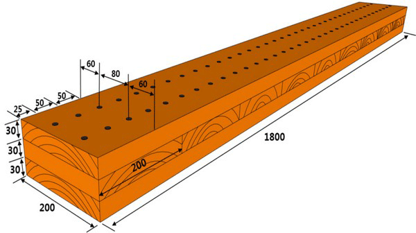
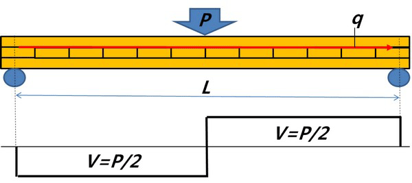
Three-layer CLT panels for bending test were manufactured using the nails as shown in Fig. 2. E7 and E5 grades were used for outer and inner laminas, respectively. The thickness, width and length of the CLT panel were 90 mm, 200 mm, 1,800 mm. The distance between nails in CLT was 50 mm with two rows. The test span (L in Fig. 3) was 1,620 mm, 18 times the thickness according to NIFoS notification No. 2017-9 (2017). The loading rate was 10 mm/min.

The shear flow through a section between laminas is calculated using Eq. (1). In Eq. (1), the shear force perpendicular to the longitudinal direction (V) is related to the load-carrying capacity of CLT (Fig. 3) as shown in Eq. (2). Thus, the load-carrying capacity of CLT is estimated from shear flow as shown in Eq. (3).

where, q = shear flow (N/mm), R = the laterial resistance of a nail (N), S = the distance between nails (mm), V = the shear force perpendicular to the longitudinal direction through the entire cross-section (N), Q = the first moment of area for a particular section of the cross-section (mm3), IT = the moment of inertia for the entire cross-section (mm4)
where, V = the shear force perpendicular to the longitudinal direction through the entire cross-section (N), Pe = load-carrying capacity of CLT (N),
where, Pe = load-carrying capacity of CLT (N),
R = the laterial resistance of a nail (N),
IT = the moment of inertia for the entire cross-section (mm4), Q = the first moment of area for a particular section of the cross-section (mm3), S = the distance between nails (mm).
3. RESULTS and DISCUSSION
The load-displacement curve of a nail connection showed a nonlinear behavior (Fig. 4). The displacement increased with load linearly in the beginning. After nails yielded, the lateral resistance was still increased up with decreased slop. However, it was slowly decreased after reaching the maximum resistance. Two lateral resistance values for a nail connection, 5% fastener offset value (ASTM D5652, 2015) and maximum value, were used to represent the lateral resistance of a nail connection (Table 1). The 5% fastener offset value and the maximum value of a nail connection were 913 N and 1,534 N, respectively.
| 5% offset value | Maximum value | ||
|---|---|---|---|
| Lateral resistance of a single nail | 913 | 1,534 | |
| Load-carrying capacity of a nail-jointed CLT | Predicted | 4,749 | 7,986 |
| Tested | - | 12,865* (7.0)** | |
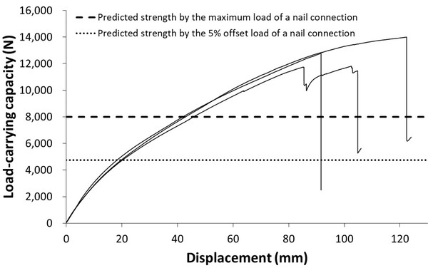
The load-carrying capacities of a nail-jointed CLT were predicted using the lateral resistance values of a nail connection and Eq. (3). The predicted values of a nail-jointed CLT were 4,749 N and 7,986 N from the 5% offset and the maximum values of a single nail resistance, respectively. In order to validate the predicted values, three nail-jointed CLTs were manufactured and out-of-plane bending test was carried out. The nail-jointed CLT showed a nonlinear behavior until failure (Fig. 5). In order to check a slip between layers in CLT by the horizontal shear force, vertical straight lines, 50 mm intervals in the longitudinal direction, were drawn using an oil-based pen on the side of the CLT specimens before testing as shown in Fig. 6. It was clear that the original straight lines did not remain straight between supports and loading points when load was applied for the nail-jointed CLT. The nonlinear behavior was caused by the flexible characteristics of nails. In other words, it shows that the nails mainly functioned to provide resistance to slippage between the layers when the CLT was subject to out-of-plane bending loads.

The load-displacement curve in Fig. 5 shows that the predicted value by the 5% offset value of a single nail was similar to the yield points on the load-displace curves of nail-jointed CLT specimens. The nail-jointed CLT specimens were yielded when the used nails were yielded. Thus, the yield point of the nail-jointed CLTs can be predicted using Eq. (3). Meanwhile, after the specimens were yielded, the load-carrying capacities of CLT specimens were continuously increased beyond the predicted value, 7,986 N, by the maximum nail lateral resistance. This phenomenon of increasing load-carrying capacity was caused by the friction between layers and the withdrawal resistance of the used nails. The continuously increased load-carrying capacity stopped by the brittle failure of a bottom lamina in a nail-jointed CLT specimen. The brittle failure of lamina shows that the tensile strength of the bottom lamina governed the maximum load-carrying capacity of the nail-jointed CLT specimen. Thus, the tensile strengths of bottom side laminas are additionally required for predicting the maximum load-carrying capacity of the nail-jointed CLT.
In this study, the maximum load-carrying capacity of nail-jointed CLT was predicted using the nail lateral resistance. However, the maximum load-carrying capacity of the nail-jointed CLT specimens was governed by the tensile strength of the bottom laminas beyond the maximum lateral resistance of the used nails. The measured maximum load-carrying capacities of the nail-jointed CLT specimens were approximately 12,865 N and these values were higher than the predicted value, 7,986 N, by the maximum nail lateral resistance. This result indicates that the maximum load-carrying capacity of the nail-jointed CLT governed by the tension failure of the bottom laminas was higher than that of nail-jointed CLT governed by the maximum lateral resistance of nails. Thus, although the used equation (Eq. 3) cannot predict exactly the maximum load-carrying capacity of the nail-jointed CLT due to the different failure mode, the equation is still valid in the viewpoint of predicting the actual strength more safely.
4. CONCLUSION
In this study, the out-of-plane bending behavior of CLT connected with nails were investigated. The nail-jointed CLT specimens were yielded when the used nails were yielded. After the specimens were yielded, the load-carrying capacities of the CLT specimens were continuously increased due to the friction between layers and the withdrawal resistance of the used nails. Finally, the nail-jointed CLT specimens were failed by the tension failure of the bottom laminas.
The load-carrying capacity of nail-jointed CLT specimens were predicted by the used nail lateral resistance. The predicted value of the nail-jointed CLT specimen by the 5% offset nail resistance was similar to the yield points on load-displacement curve of the nail-jointed CLT specimens. However, in case of the maximum load-carrying capacities of nail-jointed CLTs, the measured values were approximately 12,865 N and higher than the predicted value, 7,986 N, by the maximum nail lateral resistance. This was caused by the different failure modes. The maximum load-carrying capacity of the nail-jointed CLT specimens was predicted by the lateral resistance of the used nails, but that of the nail-jointed CLT specimens was governed by the tension strengths of the bottom laminas. This result indicates that the tension strengths of the used laminas were higher than the lateral resistance of the used nails. Therefore, although the used method in this study cannot predict exactly the maximum capacity of the nail-jointed CLT due to the different failure mode, the used method is still valid for designing a structural unit such as floor, wall and roof able to support vertical loads in the viewpoint of predicting the actual capacities more safely.


